
USEPA recently issued Effluent Guidelines Program Plan 15, which includes a focus on PFAS discharges from multiple categories. In conjunction with Plan 15, EPA has determined that revisions to the effluent guidelines and standards for the Landfills Category (40 CFR part 445) are warranted. See Section 6.3.3 of the Plan. Here are a few excerpts regarding landfill leachate:
Landfill leachate and wastewater treatment planning and resource information are available here.

SWANA is optimistic regarding the positive role modern MSW landfills can play in managing solid waste – such as carpeting and clothing – containing PFAS. By disposing of these products in landfills and effectively treating landfill leachate for PFAS removal, the solid waste industry can provide society with an effective and proven method of managing PFAS wastes.
In support of members, the SWANA Applied Research Foundation (ARF) has issued a report summarizing and analyzing management options and treatment technologies that can address PFAS chemicals contained in landfill leachate on November 10, 2021. PFAS Management and Treatment Options for Landfill Leachate is available to SWANA ARF subscribers.
The research findings presented in the resulting report are based on a comprehensive review of the literature and an analysis of the commercially-available PFAS treatment systems and other management options for landfill leachate.
The new report serves as a companion report to one published by the ARF in June 2021 on PFAS Fate and Transport in WTE Facilities, available in SWANA’s Reports List.
EPA is releasing the interim guidance for public comment. The guidance provides information on technologies that may be feasible and appropriate for the destruction or disposal of PFAS and PFAS-containing materials. It also identifies needed and ongoing research and development activities related to destruction and disposal technologies, which may inform future guidance.
The interim guidance addresses PFAS and PFAS-containing materials including:
The agency is also providing guidance on testing and monitoring air, effluent, and soil for releases near potential destruction or disposal sites. EPA’s interim guidance captures the significant information gaps associated with PFAS testing and monitoring and identifies specific research needs.
The interim guidance is intended to assemble and consolidate information in a single document that generally describes thermal treatment, landfill, and underground injection technologies that may be effective in the destruction or disposal of PFAS and PFAS-containing materials.
As further research and development occur on this issue, EPA will incorporate this increased knowledge into future versions of this guidance to help decision-makers choose the most appropriate PFAS disposal options for their particular circumstances. EPA will review and revise the interim guidance, as appropriate, or at least once every 3 years.
See the EPA website: EPA Interim Guidance on Destruction and Disposal of PFAS.
Instructions: All submissions received must include Docket ID No EPA-HQ-OLEM-2020-0527 for this rulemaking. Comments received may be posted without change to the Federal eRulemaking Portal. You may send comments by any of the following methods:
According to Waste Dive, the document is the first such federal guidance on the destruction or disposal of PFAS or PFAS-containing materials. It describes the available science used in three major techniques: deep well injection, landfilling and thermal treatment. Acknowledging uncertainty about potential environmental effects, the EPA proposed the interim storage of PFAS-containing waste until further research can “reduce the uncertainties associated with other options.”
Industry groups such as the National Waste & Recycling Association (NWRA) and the Solid Waste Association of North America (SWANA) said they are analyzing the document and discussing with their members, such as SCS Engineers what the interim guidance means for daily landfill operations. The trade groups will submit comments on the document by the Feb. 22 deadline.
On November 30, 2020, the Environmental Protection Agency announced it is aggressively addressing per- and polyfluoroalkyl substances (PFAS) in the environment. The agency announced two steps that it states would help ensure that federally enforceable wastewater monitoring for PFAS can begin as soon as validated analytical methods are finalized.
First, EPA issued a memorandum detailing an interim National Pollutant Discharge Elimination System (NPDES) permitting strategy for addressing PFAS in EPA-issued wastewater permits.
EPA’s interim NPDES permitting strategy for PFAS advises EPA permit writers to consider including PFAS monitoring at facilities where these chemicals are expected to be present in wastewater discharges, including from municipal separate storm sewer systems and industrial stormwater permits. The PFAS that could be considered for monitoring will have validated EPA analytical methods for wastewater testing. The agency anticipates being available on a phased-in schedule as multi-lab validated wastewater analytical methods are finalized. The agency’s interim strategy encourages the use of best management practices where appropriate to control or abate the discharge of PFAS and includes recommendations to facilitate information sharing to foster adoption of best practices across states and localities.
Second, EPA released information on progress in developing new analytical methods to test for PFAS compounds in wastewater and other environmental media.
In coordination with the interim NPDES permitting strategy, EPA is developing analytical methods in collaboration with the U.S. Department of Defense to test for PFAS in wastewater and other environmental media, such as soils. The agency is releasing a list of 40 PFAS chemicals that are the subject of analytical method development. This method would be in addition to Method 533 and Method 537.1 that are already approved and can measure 29 PFAS chemicals in drinking water. EPA anticipates that multi-lab validated testing for PFAS will be finalized in 2021. For more information on testing method validation, see https://www.epa.gov/cwa-methods.
EPA continues to expand its PFAS Action Plan to protect the environment and human health. To date, it has assisted more than 30 states in helping address PFAS, and the agency is continuing to build on this support. Across the nation, the EPA has addressed PFAS using a variety of enforcement tools under SDWA, TSCA, RCRA, and CERCLA (where appropriate), and will continue to protect public health and the environment.
The agency is also validating analytical methods for surface water, groundwater, wastewater, soils, sediments, and biosolids; developing new methods to test for PFAS in air and emissions; and improving laboratory methods to discover unknown PFAS. EPA is developing exposure models to understand how PFAS moves through the environment to impact people and ecosystems.
Related Information
This blog references information issued from the US EPA, Office of Public Engagement.
Across the industry, stakeholders agree the next few years will be critical in shaping how landfills deal with PFAS and how the public perceives it. Waste trade associations, scientists, and a host of organizations are in the midst of conducting a number of studies looking closely at the issue, PFAS treatment options, the positive impact of recycling, and regulatory policies.
While there are sites noted in the article, there’s no practical way for most companies and landfills to respond at this time responsibly. Additionally, landfills are unique; no two are alike. Most human exposure to PFAS occurs through contaminated food. The majority of landfill leachate is pre-treated at the landfill before going to a wastewater treatment plant, where additional treatment occurs before discharge.
According to EREF President Dr. Bryan Staley, in the article, “The relative impact of leachate as a human exposure pathway needs further evaluation to understand its relative degree of importance as it relates to health implications.”
Dr. Gomathy Radhakrishna Iyer, landfill leachate and design expert for SCS Engineers, said some operators are waiting to see what regulations may come even as they work on accounting for potential compliance issues and seeking solutions. “When the clients are thinking of upgrading their treatment plans, some are definitely taking into consideration PFAS treatment,” Radhakrishna Iyer said.
“You’re spending millions of dollars, you need to do your due diligence, right? At this point, consideration should be given to PFAS treatment during the feasibility stages,” she said.

Meet Brian Eigenberger of our Charlotte, NC office. Brian is an Associate Scientist and an Air Force Veteran recently joining the SCS Engineers team in August! Brian’s love for the outdoors sparked his interest in geology and environmental services, leading to his Bachelor of Science in Geology from the University of North Carolina in May 2019.
Brian joined the United States Air Force in September 2010, working as a maintenance scheduler for 23 F-15 fighter jets. His responsibilities were to track jet maintenance, reporting his findings to the production superintendent managing the aircraft unit, then creating maintenance schedules for each aircraft while tracking its flying hours. The work requires meticulous record-keeping and knowledge of the aircraft itself.
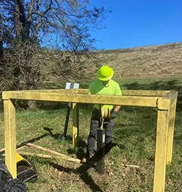
As an SCS Associate Scientist, using his USAF experience and degree, Brian now works in the office and the field. He observes landfill well installations, collects gas, soil, and liquid samples, and then prepares the scientific data findings for his clients. The information informs groundwater reports ensuring that water resources remain pristine and meet all local and federal compliance standards.
Hired during the COVID-19 pandemic, Brian said he feels lucky to work in a professional capacity on a technical team but that many of his peers are having trouble finding specialized positions. Brian had never been on a landfill before SCS. He feels the learning and mentoring bring new and exciting perspectives to his career. He knows there is much more to learn, but he is excited to be part of SCS Engineers.
Brian enjoys spending time with his golden retriever, Axel. He adopted Axel before joining the Air Force, and both were overjoyed at their reunion when he turned home from his service. The two frequently go hiking; another way Brian enjoys good company and the great outdoors!
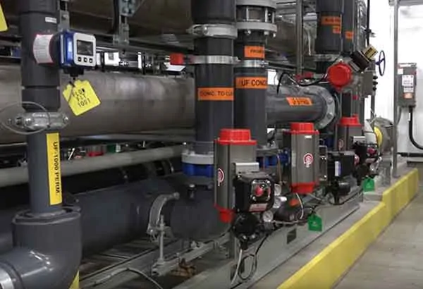
Landfill operators may add a casing pipe to their leachate force main for additional environmental protection. Consequently, the leachate force main is entirely located inside a casing pipe where the leachate force main is below ground. In the event of a leak from the leachate force main, liquids stay inside the casing pipe preventing leakage into the ground. During monitoring, checking for the presence of leachate inside of the casing pipes is routine.
For many years, I designed the installation of an HDPE monitoring manhole at each leachate removal sump station. Designed at the top of the perimeter berm, where the leachate force main is normally located, these manholes normally remain dry. The leachate force main crosses through the manhole without discharging into it. The casing pipes connecting to the manholes are open-ended at the manhole, draining directly into it. Easy to monitor, if liquids are present, you probably have a leak.
Using field operations experience, we improved the design.
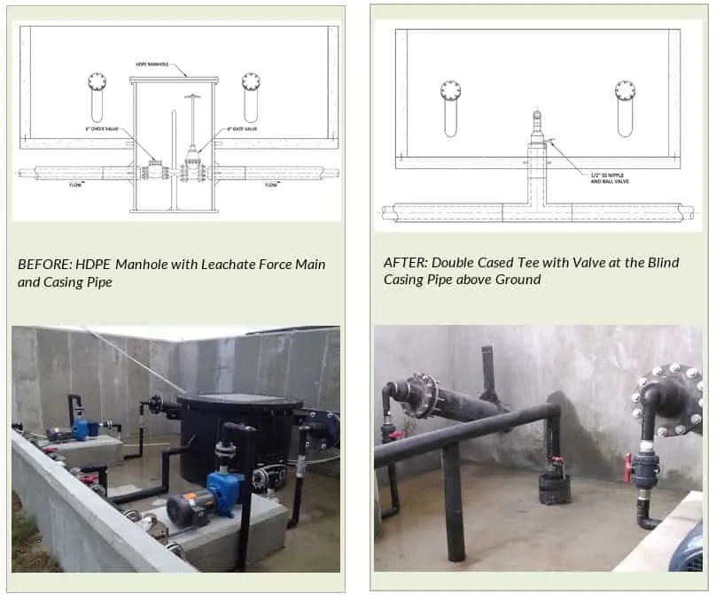
A blind casing pipe above the surface leaves the leachate line exposed for piping purposes. In this design, the casing pipe does not connect to any vessel for monitoring; instead, it has a pressure gauge or small valve on it for pressure monitoring.
If the gauge reads pressure in the casing pipe, it is indicating there is liquid inside the casing pipe; leachate is leaking from the force main and filling the casing pipe causing the pressure to build. If using a valve, monitoring is opening the valve to look for liquid coming out of the casing pipe. Regularly monitored pressure gauges or valves is a standard operating procedure and easily accomplished.
By Ali Khatami
MSW sanitary landfills constantly face the issue of aesthetics due to leachate seeping out of the landfill slopes. Of course, the problem goes away after the construction of the final cover, but the final cover construction may not take place for many years after seeps show up on slopes. To the public, leachate seeps represent a problem with the design of the landfill and possible malfunction of the leachate collection system below the waste, which is an incorrect perception. Such arguments are common and difficult to counter.
Landfill operators use different means to control leachate seeps from landfill slopes and to clean up the unpleasant view of the seep as soon as they can. Innovative solutions to address the issue have been observed and noted in the industry. The degree of effectiveness of the solution to some extent depends on the amount of money spent to address the problem. Some landfills are located in rural areas and the operator may not mind the unpleasant appearance of the slopes, so naturally no urgency in addressing the issue or no money available to take care of the problem.
The environmental side of the leachate seep issue is the impact to surface water quality. If leachate seeps remain unresolved, liquids coming out of slope may eventually reach the landfill perimeter and mix with stormwater in the landfill perimeter ditch. At that point, the operational issue turns into a compliance issue, and regulatory agencies get involved. If the public around the site is on top of their game concerning their opposition to the landfill, they can take the non-compliance issue and turn it into a political issue. At that point, the landfill operator finds himself or herself on the hot plate dealing with the agency and the public on an environmental impact matter.
It always makes sense to stay ahead of the issues and address any potentially sensitive condition before it turns into a major problem. As discussed above, addressing leachate seeps can be done in many different ways, and the operator needs to be prepared to fight for funds to address leachate seeps as they appear on slopes. Availability of funds and willingness of the operator to take necessary action are the primary required elements to stay ahead of the game.
SCS has developed methodologies to address all sorts of leachate seeps on landfill slopes and is uniquely equipped to assist you with a solution. Reach out to a local SCS office for a consultation if you have leachate seep problem at your site.
In this blog, we discuss the basics of various wastewater treatment methods in use today including process design parameters, advantages, disadvantages, and costs. Some of the wastewater treatment methods are better suited to landfill leachate treatment than others. For example, the traditional activated sludge wastewater treatment technology, discussed in this article is not suitable for landfill leachates, but it has been modified and improved so that its close cousin – for example the membrane bioreactor (MBR) – is much better suited for landfill leachate treatment. The blog is intended for those who manage projects that include leachate treatment but who are not wastewater or process engineers. We start by grouping treatment systems into three basic categories; biological, physical and chemical. Our first blog in the series focuses on biological treatment.
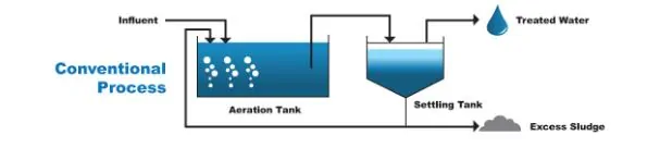
The oldest treatment technology for sanitary wastewater, with the longest track record, is biological treatment. It is effective for treating the type of wastewater generated by humans because it uses naturally occurring microbes to reduce organics, ammonia and other naturally occurring impurities. The modern version of this time-honored biological treatment process (from the 1960s forward) is known as the basic activated sludge (BAS) process. This is the type of treatment that is used at large publicly owned treatment works (POTWs) and the same form of treatment can be used, on a smaller scale, for landfill leachate. The wastewater to be treated, whether it is sanitary wastewater or landfill leachate, contains organic compounds, nutrients (e.g., nitrogen and phosphorus) and naturally occurring microorganisms. When given the right balance of soluble food, temperature, and oxygen, the microorganism population can be increased rapidly. In multiplying their numbers, the microorganisms absorb some of the food sources (organics) in the wastewater for energy and convert that to new cell mass (through cell growth and reproduction), carbon dioxide (CO2), and water.
The actual BAS treatment process involves pumping the raw wastewater through an open tank, aerating and agitating the liquid by mechanically adding air or oxygen typically through a set of fine bubble diffusers, then after a prescribed time, passing that water to another tank called a clarifier. The process is illustrated below.
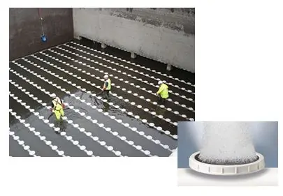
The dispersion pattern and the buoyancy of the bubbles promote mixing of the tank contents to ensure the bugs are getting adequate oxygen. An example of a bubble diffuser disc and a typical bubble diffuser bank layout is shown in the two photos below.
A process called nitrification also occurs in the aeration tank. Nitrification is a microbial process by which reduced nitrogen compounds (primarily ammonia) are sequentially oxidized to nitrite and nitrate by the species of microbes called Nitrosomonas, Nitrosospira, Nitrosococcus, and Nitrosolobus.
A biological system, such as a BAS has a susceptibility to some chemicals in leachate that in certain concentrations can be toxic to the “bugs.” For example, high concentrations of ammonia (NH3), chlorides or toxic substances can be harmful. Also, the treatment effectiveness of biological systems drops off significantly at a wastewater temperature lower than about 50 degrees Fahrenheit. Rapid changes in concentrations of these chemicals (or spikes) also can be harmful.
In the clarifier, flocculation chemicals are added to the water to aggregate and help to settle out the cell mass. The cell mass, almost 99% water, is called sludge. Periodically some of the sludge from the clarifier is removed and brought to the front of the process where this “activated” sludge (i.e., air enriched and microbes are alive) is used to seed the incoming wastewater with robust microbial growth and boost the growth of existing organisms that break the organics down. The balance of sludge (called “biosolid”) is removed from the clarifier and is typically dried, disinfected through use of high pH material and or heat and is then used as a soil conditioner directly or as a fertilizer ingredient.
The laboratory measurement of the amount of oxygen that microorganisms use to convert the food to new cell mass is called the biochemical oxygen demand (BOD5). The five day long BOD test was the earliest measure of the organic strength of wastewater and is a rough indication of how much energy (and relative cost) will be expended to treat the wastewater. Landfill leachate is typically considered a strong wastewater compared to municipal wastewater which is considered weak to moderate strength. Many municipal wastewaters are weak because they are heavily diluted with groundwater and infiltration of rainfall.
A key design parameter for any BAS process is the Mixed Liquor Suspended Solids (MLSS). The MLSS is the concentration of suspended solids in the aeration tank. The suspended solids are mostly the active microorganisms that do the work of decomposing the organic substances. The MLSS for a BAS is typically 4,000 to 6,000 mg/l.
Many other water chemistry aspects must be considered with the BAS process. However, these have not been included to simplify this explanation.
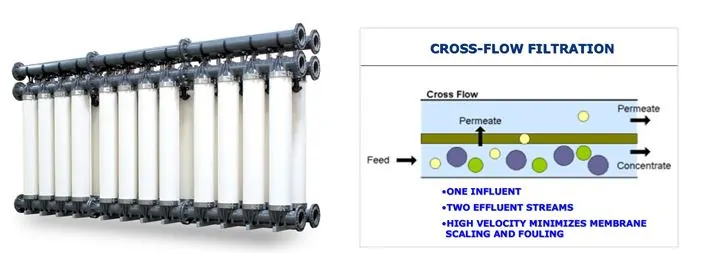
Over the decades the BAS process has been modified to address the many different types and strengths of wastewater, increase energy efficiency, reduce treatment times, improve resilience to shock loads, and pollutant removal effectiveness. You may have heard them called Sequencing Batch Reactor (SBR), or powdered activated carbon treatment (PACT). These are variations of the BAS process. Because landfill leachate is somewhat similar in chemical makeup to municipal wastewater, with typically higher chemical constituent concentrations, the landfill sector has successfully borrowed municipal treatment technology. An improvement to the BAS process that started showing up at landfills about 15 to 20 years ago is known as the Membrane Bio-Reactor (MBR) shown here.
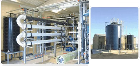
The MBR took advantage of advances in micro-manufacturing capability in perfecting synthetic membrane filtration fabric. The membrane, when incorporated in the treatment process, eliminates the need for a clarifier. The membrane works by separating insoluble solids from the water. The advantages of the membrane filtration include;
The membranes are manufactured either as a cylinder shown below-left, or as a flat plate used in a rack outside the BAS reactor, or immersed in the BAS reactor. The diagram shown on the right illustrates the membrane filter process.
Some disadvantages of the MBR can include:
The MBR can manage a much higher MLSS than a conventional BAS; a typical maximum for a BAS is about 4,000 mg/l as compared to around 16,000 mg/l or more in an MBR. The higher MLSS allows for treating a stronger waste stream, and the system has better cold weather and shock load resistance. It can do this because the solids eventually are removed by a membrane. In the BAS process, the chemical treatment in the clarifier forms a large volume of sludge (organic chemicals + microorganisms) that has to be kept in balance by frequent sludge wasting out of the system. Without this wasting, the sludge volume recycled to the aerobic tank would overwhelm the aeration capacity, and the process would collapse. A process flow diagram may look like the one below.
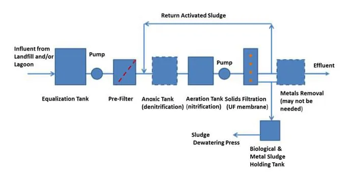
Typically, landfill leachate may need other treatment processes to supplement an MBR system to meet requirements for reducing specific pollutants and other parameters before the treated effluent can be released to the receiving water. One of the key parameters is ammonia (NH3) nitrogen.
Ammonia is produced in the landfill by microorganisms utilizing the organic substances in waste for energy and reproduction in an anaerobic (without oxygen) environment. In an aerobic environment outside the landfill, ammonia can be oxidized by bacteria in a process called nitrification, converting ammonia to nitrite and then to nitrate. When combined with enough phosphorus, nitrates released to surface waters in high enough concentrations can promote algae blooms. The algae blooms typically die off from cold, or their normal lifespan. Large amounts of dead algae compete for oxygen with fish and other wildlife. The result can be fish kills, which can further worsen the water body oxygen depletion problem.
So, in addition to the ammonia being converted to nitrite and then nitrate, the nitrate-nitrogen typically must be removed before discharge of the treated wastewater effluent to surface water. The nitrite and nitrate removal process is known as denitrification and involves reducing the nitrate to nitrogen gas which is inert and not harmful to the environment. Denitrification in the leachate treatment process can be accomplished either by ion exchange, chemical reduction, or biological processes.
The biological method is very common and is typically conducted in a tank known as the anoxic tank. The anoxic tank typically has a filter bed containing the nitrate conversion microorganisms where the nitrate-laden water is passed through for treating. No air is added to maintain an environment that is suitable for the heterotrophic microorganisms that convert nitrate to nitrogen gas. Methanol or acetic acid is typically added to provide a food source for the denitrifying culture in the filters.
Some other key process parameters for the MBR that will affect process sizing and footprint includes the following:
For example, using these unit costs an MBR plant rated at 65,000 GPD would have a basic capital cost of $1.2 to $1.4 million. This does not include a building. The annual operating cost of chemicals and energy only (not including labor), with 90% availability would be $640K to $1.07 million. Extra costs would include; a building if desired or necessary, electrical supply, equalization tank, yard piping, bench and pilot tests, and engineering. These are rough figures to give the reader a sense of the magnitude of costs. Actual costs will differ. It is always best to check with one or more vendors on the unit costs they experience with installations that they provide.
Biological processes have been adapted successfully from the municipal wastewater industry by the wastewater equipment manufacturers who service the solid waste industry to treat landfill leachate. They form the basis of a viable treatment platform that can be expanded depending on the effluent requirements and other design goals. By coupling high-quality membrane filters to remove solids with the BAS-type treatment modifications, MBR plants are revolutionizing leachate treatment. MBR plants are a more efficient and more effective treatment of higher strength leachates. Many vendors are offering modular systems that fit well with the leachate production and growth typical at landfills.
In our next blog, we will discuss membrane filtration systems that are increasingly finding application where leachate has to meet tough discharge standards. Follow SCS Engineers on Twitter, LinkedIn, or Facebook.
Learn more about Liquids Management – Leachate Services
Deep injection wells (DIW) mean different things in different parts of the country. In the midwest DIWs have been used for decades to dispose of industrial wastewaters, mining effluent, and produced water from oil and gas production activities and are from 3,500 feet to more than 10,000 feet deep. In Florida, deep injection wells have been used since the 1960s; however, they are used to dispose of treated municipal wastewater, unrecyclable farm effluent, and in some cases landfill leachate. DIWs in Florida range from 1,000 feet to around 4,500 feet deep.
This is a two-part blog, the first part discussing what constitutes a DIW, their general features, their cost relative to other wastewater management alternatives, and the range of industrial wastewaters suitable and safe for disposal. The second part, covered in the next SCS Environment issue, will be on the challenges for deep well developers created by public and environmental organizations, and strategies to counter misinformation and means to obtain consensus from stakeholders.
A DIW construction is a series of casings set in the ground where the initial casing starts out large and subsequent casings become smaller in diameter, progressively telescoping downward. Casing materials are typically steel alloys or fiberglass for better chemical resistance. As a casing is set and rock is drilled out, the next casing is set and cemented with a chemically resistant grout. The process continues with each progressively deeper casing. These redundant “seals” are what keep the injected liquid from escaping into the protected aquifers.
A DIW typically has three upper casings to protect the aquifers and isolate the wastewater to the desired disposal zone. The inner casing, called the injection tube, extends to the injection zone. Mechanical packers seal the space between the injection tube and the last casing with the annular. The resulting annular space is filled with a non-corrosive fluid. This fluid is put under pressure to demonstrate the continuous mechanical integrity of the well. The annulus is monitored for potential leaks, which would register as a loss in pressure and promptly stop the injection. Figure 1 is a simplified view of a DIW casing system used in south Florida.
Vertical turbine pumps working in conjunction with a holding tank, which is a used to smooth out the fluctuating flow of the wastewater feed pumps, propel the liquid down the well. As part of the permitting efforts, a chemical compatibility study is conducted to determine the level of pre-treatment if any to protect the well components and minimize downhole plugging. Municipal wastewater effluent is regulated differently and must receive at least secondary treatment before injection.

In the Midwest, DIWs are constructed to the same EPA criteria with a wide range of operating conditions. Some wells take fluid under gravity with no pumping, while others require higher pressure pumps that exceed 2,500 psi for injection. This blog focuses on wells used in Florida and typical fluid types and operational parameters.
In central and south Florida the injection zone lies below the underground sources of drinking water (USDW) which is the depth at which water with a total dissolved solids (TDS) concentration exceeds 10,000 parts per million (ppm); or the “10,000 ppm line”. This water is considered to be unusable in the future as a drinking water source. In parts of Florida, the injection zone is dolomite overlain by a series of confining units up to 1,000 feet thick made up principally of limestone with permeability several orders of magnitude less than the injection zone. (1)
In central and south Florida the target injection interval is the “Boulder Zone,” reportedly named because drilling into the formation often broke off pieces of the formation and made drilling difficult. The Boulder Zone is also known as the lower portion of the Floridan Aquifer. Later down-hole imaging technologies revealed this zone to be characterized by highly fractured bedrock and large karstic caverns, and the ability to inject relatively high flow rates with relatively little backpressure. It is not uncommon for Florida DIWs to have well flow rates exceeding 15 million gallons per day (MGD) and backpressures ranging from 30 up to 100 pounds per square inch (psi).

The versatility of the DIW in Florida to accommodate numerous different types of wastewater is an advantage. DIWs are being used on a large variety of waste streams that continues to expand, including:
Any wastewater considered for disposal must be compatible with the target formation and the final casing material. Therefore, depending on the wastewater, it may be straightforward to use existing industry references to confirm compatibility. In some cases, laboratory bench tests may be necessary to confirm compatibility.
Compatibility also includes the potential for creating unwanted microbial growth and scale formation within the injection interval. Growth and scale can happen with effluent containing sulfur or ammonia, two food sources for microorganisms or wastewaters supersaturated with minerals. Unless planned for and evaluated properly, both of these items have the potential to grow and clog the formation around the well, significantly reducing flow and increasing back pressure. This can result in higher energy costs, regulatory action and significant, unplanned costs to rehabilitate the well.
Another significant aspect of municipal wastewater is that they are primarily composed of freshwater and thus when injected into the highly saline Boulder Zone or similar saline zones, will tend to have a vertical migration component because of the density difference and greater buoyancy than the target zone. A few wells have been taken out of service because the seals designed to prevent this migration failed and allowed wastewater to seep upwards into the USDW.
The US EPA Underground Injection Control (UIC) program is designed with one goal: protect the nation’s aquifers and the USDW. There are several protective measures in a DIW that are intended to meet this objective;
The U.S. EPA conducted a study in 1989-1991 of health risks comparing other common and proven disposal technologies to deep wells injecting hazardous waste. The U.S. EPA concluded that the current practice of deep well injection is both safe and effective, and poses an acceptably low risk to the environment. In 2000 and 2001 other studies by the University of Miami and U.S. EPA, respectively, suggested that injection wells had the least potential for impact on human health when compared to ocean outfalls and surface discharges(3). William R. Rish examined seven potential well failure scenarios to calculate the probabilistic risk of such events.These scenarios included four types of mechanical failures, two breaches of the confining units, and the accidental withdrawal of wastes. The overall risk was quantified by Rish as from 1 in 1 million (10-6) to 1 in 100 million (10-8) (4), which is no greater than the current EPA risk criteria for determining carcinogen risk. As a comparison, 10-6 is the same risk level used by EPA for contaminants in soil or groundwater that are a known carcinogen.
There are several studies in Florida conducted by researchers and practitioners in the deep injection well field to assess the actual potential for municipal wells to contaminate the USDW. The maximum identified risk associated with injection well disposal of wastewater in south Florida is the potential migration of wastewater to aquifer storage and recovery (ASR) wells in the vicinity of injection wells (Bloetscher and Englehardt 2003; Bloetscher et al. 2005).
In a 2007 study, 17 deep wells in south Florida, used for municipal waste disposal, that had known upward migration into the USDW, were evaluated to develop a computer model to simulate these phenomena and extrapolate vertical migration over longer time periods. The results indicated that the measured vertical hydraulic conductivities of the rock matrix would allow for only minimal vertical migration. Even where vertical migration was rapid, the documented transit times are likely long enough for the inactivation of pathogenic microorganisms (5).
In a 2005 study of 90 South Florida deep injection wells, the authors took actual field data and constructed a computer model calibrated to actual operating conditions. The intent was to model performance of two injection wells in the City of Hollywood, Florida that the authors were familiar with and to determine the likelihood of migration, and what might stop that migration. Density differential and diffusion were likely causes of any migration. No migration was noted in Hollywood’s wells. The preliminary results indicate that Class I wells can be modeled and that migration of injectate upward would be noticed relatively quickly (3).
A deep injection well lifecycle cost compares favorably with other traditional waste treatment and disposal techniques. A life-cycle cost includes the capital cost and operating and maintenance costs for the useful life of the system. On a recent project, the wastewater for disposal was groundwater contaminated with ammonia nitrogen from a former landfill. The estimated groundwater recovery rate and the deep injection well disposal rate was calculated to be 1.2 million gallons per day (MGD). The proposed deep well was designed to have a final casing of 12-inch diameter, an 8-inch diameter injection tubing to a depth of 2,950 feet, and below that approximately 550 feet of open bore hole. The lifecycle cost estimate comparison to other viable technologies is shown in the Table below.

In this case, there were no projected revenues, so the alternative with the lowest net present value (NPV) would technically be the preferred alternative. Even though the aerated lagoon had the lowest NPV, it was ultimately judged too risky with a long break-in treatment period and significantly more space for treatment ponds needed.
The increasingly stringent surface water discharge standards are an ongoing challenge for industries generating a wastewater stream. DIW’s should be considered as a potentially viable option for long-term, cost-effective wastewater disposal, where a viable receiving geologic strata exists and when wastewater management alternatives are evaluated. In Florida, they currently provide an environmentally sound disposal option for many regions.
Within the SCS Engineers’ website, you will find the environmental services we offer and the business sectors where we offer our services. Each web page offers information to help you qualify SCS Engineers and SCS’s professionals by scientific and engineering discipline.
We provide direct access to our professional staff with whom you may confidentially discuss a particular environmental challenge or goal. Our professional staff work in partnership with our clients as teams. We are located according to our knowledge of regional and local geography, regulatory policies and industrial or scientific specialty.