Gas production during the active life of landfills is a well-known phenomenon, with many means to collect and dispose of landfill gas already developed and implemented in landfills across the world. What is less known in the industry is that concentration of landfill gas near the lining system can reach significant levels, causing high gas pressure developing in, and around, the leachate collection drainage layer. High-pressure gas can potentially fill voids within the drainage layer (geocomposite or sand), causing conditions impeding flow in the drainage layer, adversely affecting the free flow of leachate.
Leachate collection pipes encased in gravel are pervious media through which landfill gas can easily travel and high pressures transfer to the sump area. Such conditions can cause significant odors near the sump due to emissions of landfill gas through the drainage layer and the overlying sand layer on the side slope of the perimeter berm near the sump. In addition, high-pressure builds in the riser and cleanout pipes.
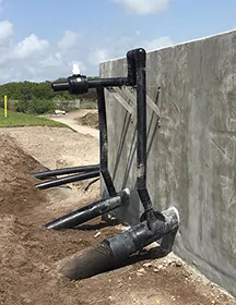
Consider an effective gas pressure removal system in the sump by installing vertical pipes on the riser pipes behind structures, on top of the perimeter berm, shown here. The vertical pipes are blind-flanged initially at cell construction completion. If the gas pressure build-up becomes significant, or odors are detected in the sump area, the landfill operator connects the vertical pipes to a vacuum source near the sump.
Using a connecting pipe to a vacuum source can also be used to discharge condensate from the gas collection and control system directly into the leachate collection riser pipe.
For a double lining system, with a riser pipe in the primary system and another in the secondary system, both risers will have vertical pipes on them, and both connected to the vacuum source.
However, condensate flowing down the connecting pipe from higher elevations toward the risers should not enter the secondary system. Block it by using a manifold, as shown in the image.
Operators may have a vertical pipe installed on the leachate collection pipe cleanout to apply vacuum directly to the leachate collection pipe.
Keeping gas pressure low in and around the leachate collection pipe promotes the free flow of leachate through the geocomposite or granular medium drainage layer to the leachate collection pipe, and improves leachate removal from the disposal cell.
Using gas removal piping at leachate sumps is highly recommended for warm or elevated temperature landfills where efficient leachate removal from the leachate collection system is another means for controlling landfill temperatures.
 About the Author: Ali Khatami, Ph.D., PE, LEP, CGC, is a Project Director and a Vice President of SCS Engineers. He is also our National Expert for Landfill Design and Construction Quality Assurance. He has nearly 40 years of research and professional experience in mechanical, structural, and civil engineering.
Learn more at Landfill Engineering and Leachate Management
Typical designs of landfill disposal cells include two slopes, one at the landfill base and the other along the leachate collection pipe. The drainage layer covering the entire cell base area follows the slope of the base toward the leachate collection pipe, and the flow in the leachate collection pipe follows the pipe slope. With the growth in the application of geosynthetics in the landfill industry, the majority of modern landfill designs include a geocomposite drainage layer, unless a granular material is readily available at an economically viable cost in the area of the landfill, which can replace the geocomposite material.
Base slopes are designed to maintain a positive flow toward the leachate collection pipe after long-term settlements of the foundation. In addition to this requirement, sometimes solid waste rules require either a minimum slope at the time of the design or a minimum slope after foundation settlement.
Regulatory agencies go through a comprehensive review process to make sure that such matters are addressed in a solid permit application involving the design of new disposal cells. However, sometimes designers propose slopes that seem to be significantly steeper than the minimum values required in the rules with no supporting foundation settlement analysis to justify the need for the steeper slopes. Slopes steeper than what is required (technically or regulatory-wise) have two drawbacks: 1) loss of the airspace which otherwise would be captured with a less steep slope; 2) lower liquid transmissivity in the geocomposite drainage layer. Laboratory experiments have shown that transmissivity of geocomposites reduces as gradient increases. This phenomenon may be related to higher turbulence in the flow of leachate through the geocomposite voids. The flow path of liquids within the geocomposite structure includes vertical and horizontal barriers that liquid flows around or over within the geocomposite thickness. Steeper slopes increase the velocity of liquids through the geocomposite, and higher velocity makes the flow more turbulent, and the higher turbulence reduces transmissivity.
One of the most important regulatory requirements on a landfill’s bottom lining system drainage layer is that the maximum head of leachate over the liner should not exceed 1 ft. When this requirement was developed, the consensus was that the drainage layer consisted of granular materials. Later, when geonets and geocomposites entered the market, the unwritten consensus among solid waste engineers and regulators was that the maximum head of leachate at the base should not exceed the thickness of the geonet or geocomposite drainage layer. With that in mind, the reduction in transmissivity of geocomposite laid over steeper slopes can adversely impact the maximum leachate head over the liner. Maximum leachate head is normally calculated from the theoretical model (along with some simplifications to disregard very small terms in the theoretical model) developed by C. A. Moore, J.P. Giroud, B. M. McEnroe, and others. One of these models was later incorporated into the Hydrologic Evaluation of Landfill Performance (HELP) model that is currently used by almost all solid waste engineers in the industry. Such model includes a parameter called hydraulic conductivity which is calculated from the transmissivity value of the geocomposite drainage layer. When transmissivity value reduces due to steeper slope at the base, the hydraulic conductivity reduces in turn as well. In the Moore’s and Giroud’s models, the maximum head of leachate is somewhat inversely proportional to the square roots of the hydraulic conductivity, which means the reducing hydraulic conductivity results in an increase in the maximum head of leachate passing through the geocomposite. The relationship between the leachate maximum head and the hydraulic conductivity is a lot more complicated in McEnroe’s model.
It’s recommended that the minimum base slope be initially determined based on foundation settlement. Then, the calculated minimum slope compared to the required value in the solid waste regulations, if any. If the rules require a minimum slope at the time of the design, pick the regulatory value if higher than the calculated minimum slope; otherwise, pick the calculated minimum slope. If the rules require a minimum slope after foundation settlement, then add the calculated minimum slope to the minimum slope in the rules and use that in the design.
A 1 percent slope at the base, provided all requirements are met, seems to be a suitable slope. The geocomposite transmissivity at 1 percent is higher than the transmissivity at 2 percent, and the space difference between the 1 percent and 2 percent slopes can be added to the landfill airspace for waste disposal.
Author: Ali Khatami, PhD, PE, LEP, CGC, is a Project Director and a Vice President of SCS Engineers. He is also our National Expert for Landfill Design and Construction Quality Assurance.
Landfill Design – Information and Case Studies
One general problem that is encountered in traditional designs is the potential for clogging of geotextiles in the vicinity of the leachate collection pipes.
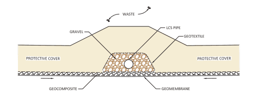
Traditionally, leachate collection pipes are encased in gravel, wrapped in geotextile, and positioned above the leachate collection system geocomposite drainage layer inside a trench or at the trough of the bottom of a cell. In a traditional design, leachate travels through the geonet component of the geocomposite and reaches the leachate trench where the leachate collection pipe is located. Here, leachate must flow out of the geocomposite, through the upper geotextile component, and then through the geotextile wrapped around the gravel, before entering the gravel and eventually flowing through the pipe. The flow through the geotextiles is concentrated in small areas on the two sides of the leachate collection pipe-gravel-geotextile wrap. Considering the large volume of leachate that follows this path over the life of the cell, it is evident why traditional designs are doomed to clog.
The clogging impedes the free flow of leachate from the geocomposite drainage layer to the leachate collection pipe. As the clogging occurs, the leachate must find a new flow path (most likely further back from the collection pipe), and flow out of the geocomposite, through the geotextile wrap at a different location, and eventually enter the gravel and pipe. This new location will eventually clog as well for the same reasons that the initial location was clogged. This process continues until the geotextile within the leachate trench becomes completely clogged and the system loses functionality. Unfortunately, the periodic cleaning of leachate collection pipes (usually every few years) cannot address this issue because the problem is outside the pipe and the high-pressure jets inside the pipes do not reach the clogged locations.
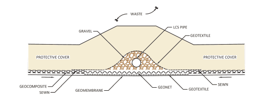
The solution is to eliminate geotextiles from the flow path of the leachate, extending from the geocomposite drainage layer to the leachate collection pipe. Over the past several years, SCS has successfully designed and constructed numerous landfill cells with no geotextile in the flow path of leachate from the geocomposite drainage layer to the leachate collection pipe. The design follows the “Rule of Transmissivities” which dictates that a proper design should provide the free flow of leachate from one medium to another and that only occurs when the transmissivity of the latter medium is equal to or greater than the transmissivity of the former medium. If a design does not satisfy the Rule of Transmissivities, there may be potential for clogging, bottlenecking of flow, and other consequences resulting from impeded flow in the system.
SCS Engineers is a leader in the design of landfill lining systems, and we have experience with issues that may not be familiar to other firms. If you are interested in the design of a leachate collection system at your facility, please contact SCS. Our professional engineers will gladly review your design and make recommendations if needed. We can identify potential issues and improve designs to prevent future problems and maintenance during the life of your facility.
Questions? Contact Ali Khatami, PhD, PE, LEP, CGC, is a Project Director and a Vice President of SCS Engineers. He is also our National Expert for Landfill Design and Construction Quality Assurance. He has nearly 40 years of research and professional experience in mechanical, structural, and civil engineering. Dr. Khatami has acquired extensive experience and knowledge in the areas of geology, hydrogeology, hydrology, hydraulics, construction methods, material science, construction quality assurance (CQA), and stability of earth systems. Dr. Khatami has applied this experience in the siting of numerous landfills and the remediation of hazardous waste contaminated sites.
Read more here. Rule of Transmissivities at Material Interfaces in Landfill Leachate Collection Systems, in Talking Trash
Corporate Headquarters