It’s been 10 years since the first Research, Development, and Demonstration (RD&D) Plans were approved allowing liquids to be applied to municipal solid waste landfills in Wisconsin. What have we learned?
Under an approved RD&D Plan, landfill operators can apply liquids other than recirculated leachate to the waste at municipal solid waste landfills. The RD&D Rule was published by US EPA in 2004, and states had the option of adopting the rule and issuing RD&D approvals. Wisconsin was an early adopter, and 13 of the approximately 30 landfill sites in the US with RD&D approvals are in Wisconsin.
This presentation will look at data from the Wisconsin landfills with RD&D Plans. Each site is required to report annually on a very detailed basis. For this presentation we will zoom out and look at the data on an aggregated basis to address big-picture questions. What are the trends in volumes applied for leachate recirculation versus RD&D Liquids? How do these volumes compare with precipitation? What liquid waste streams have been accepted and how have they been applied? How has RD&D liquid application affected landfill gas generation?
We will also provide an update on the regulatory status of the RD&D rule. On May 10, 2016, a final federal rule was published that revised the maximum permit term from 12 years to 21 years; however, WDNR will have to adopt this change in order for it to be available to Wisconsin landfills.
High-density polyethylene pipes have been used for landfill leachate collection and conveyance lines for several decades because of the chemical compatibility of HDPE material with many different types of liquids and chemicals. Designing a leachate collection system for a landfill disposal cell involves numerous engineering analyses of different components involved in collecting and conveying leachate. One of the important engineering evaluations is a determination of structural stability of HDPE leachate collection pipes at the bottom of the landfill.
Structural Stability of HDPE Pipe
Modern landfills are gradually becoming larger and deeper; deeper landfills will naturally impose a higher surcharge loading on the HDPE leachate collection pipes below the waste column. Engineering methodologies for the structural stability evaluation of HDPE pipes with significant surcharge loading have been around as long as HDPE pipes have been in production.
There are three criteria used when evaluating the structural stability of HDPE pipes; wall crushing, wall buckling, and ring deflection. Wall crushing can occur when the stress in the pipe wall, due to external vertical pressure, exceeds the compressive strength of the pipe material. Wall buckling, a longitudinal wrinkling in the pipe wall, can occur when the external vertical pressure exceeds the critical buckling pressure of the pipe. Ring deflection is the change in vertical diameter of the pipe as the pipe deforms under the external pressure. Empirical formulas by HDPE pipe manufacturers or researchers are available to check each criterion.
SDR 11 vs. SDR 17 HDPE Pipe
When a structural stability evaluation involves high surcharge loading on the pipe, an engineer may automatically select SDR 11 HDPE pipe without going through an evaluation process. The engineer’s reasoning is that the higher wall thickness of SDR 11 pipe, as compared to SDR 17 pipe, is the logical choice because it provides a higher level of structural stability to the pipe. In the case of wall bucking and wall crushing, where the pipe strength in these two criteria is inversely proportional to the SDR value, the engineer is making the right choice. The strength is greater for the lower SDR value that represents thicker pipe wall thickness; making SDR 11 stronger than SDR 17.
However, in the case of ring deflection, the pipe strength is not a function of SDR, but a function of another parameter called allowable ring deflection. The allowable ring deflection value varies from one SDR to another and is generally reported by pipe manufacturers. The allowable ring deflection for SDR 17 pipe is greater than all other SDR pipes, which makes SDR 17 pipe stronger when considering ring deflection. SDR 17 pipe is also the most commonly used HDPE pipe in the landfill industry, being lighter in weight per unit length of the pipe than SDR 11, thus making it less expensive than SDR 11 pipe.
Which Is Best For My Landfill?
SCS Engineers recommends that landfill engineers consider SDR 17 pipe as the first choice for use as a leachate collection pipe below the waste column, and then other SDRs if SDR 17 does not pass the three structural stability criteria mentioned above.
Read more blogs by Ali Khatami, click here and type “Advice from the Field” in the search box.
We continue SCS’s Advice from the Field blog series with guidance from an article in MSW Magazine by Daniel R. Cooper, Jason Timmons, and Stephanie Liptak.
The authors of a recent article in MSW Management Magazine present engineering ideas that provide for more efficient construction of a GCCS. Gas system operators will benefit by having fewer pumps to operate and maintain and shallower headers that are more easily accessible. Odor management will be easier along with other benefits.
Read the full article here to learn about the design elements for maximizing long-term benefits, impacting: bottom liners, location of the blower/flare station, leachate risers, extraction well targets, and external header piping.
The past few decades of advancements in developing new drainage media have led to the use of geocomposites as the primary drainage layer above the bottom lining system geomembrane. However, you need to be watchful for the free flow of leachate through the thin layer of geocomposite under high gas pressures near the bottom lining system.
Short of investigations and clear guidelines for addressing high gas pressure near the bottom lining system, you can use a gas pressure relief system near the bottom in future new disposal cells. The pressure relief system can simply include a few perforated high-density polyethylene pipes laid in parallel directly above the soil layer placed above the bottom lining system drainage layer, as shown in the schematic.
About the author: Dr. Ali Khatami
Landfill Leachate Management Services
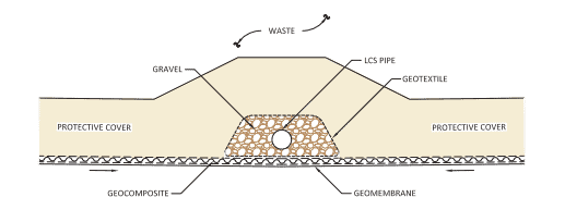
One general problem that is encountered in traditional designs is the potential for clogging of geotextiles in the vicinity of the leachate collection pipes.
Traditionally, leachate collection pipes are encased in gravel, wrapped in geotextile, and positioned above the leachate collection system geocomposite drainage layer inside a trench or at the trough of the bottom of a cell. In a traditional design, leachate travels through the geonet component of the geocomposite and reaches the leachate trench where the leachate collection pipe is located. Here, leachate must flow out of the geocomposite, through the upper geotextile component, and then through the geotextile wrapped around the gravel, before entering the gravel and eventually flowing through the pipe. The flow through the geotextiles is concentrated in small areas on the two sides of the leachate collection pipe-gravel-geotextile wrap. Considering the large volume of leachate that follows this path over the life of the cell, it is evident why traditional designs are doomed to clog.
The clogging impedes the free flow of leachate from the geocomposite drainage layer to the leachate collection pipe. As the clogging occurs, the leachate must find a new flow path (most likely further back from the collection pipe), and flow out of the geocomposite, through the geotextile wrap at a different location, and eventually enter the gravel and pipe. This new location will eventually clog as well for the same reasons that the initial location was clogged. This process continues until the geotextile within the leachate trench becomes completely clogged and the system loses functionality. Unfortunately, the periodic cleaning of leachate collection pipes (usually every few years) cannot address this issue because the problem is outside the pipe and the high-pressure jets inside the pipes do not reach the clogged locations.
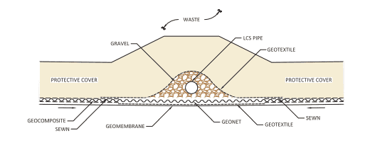
The solution is to eliminate geotextiles from the flow path of the leachate, extending from the geocomposite drainage layer to the leachate collection pipe. Over the past several years, SCS has successfully designed and constructed numerous landfill cells with no geotextile in the flow path of leachate from the geocomposite drainage layer to the leachate collection pipe. The design follows the “Rule of Transmissivities” which dictates that a proper design should provide the free flow of leachate from one medium to another and that only occurs when the transmissivity of the latter medium is equal to or greater than the transmissivity of the former medium. If a design does not satisfy the Rule of Transmissivities, there may be potential for clogging, bottlenecking of flow, and other consequences resulting from impeded flow in the system.
SCS Engineers is a leader in the design of landfill lining systems, and we have experience with issues that may not be familiar to other firms. If you are interested in the design of a leachate collection system at your facility, please contact SCS. Our professional engineers will gladly review your design and make recommendations if needed. We can identify potential issues and improve designs to prevent future problems and maintenance during the life of your facility.
Questions? Contact Ali Khatami, PhD, PE, LEP, CGC, is a Project Director and a Vice President of SCS Engineers. He is also our National Expert for Landfill Design and Construction Quality Assurance. He has nearly 40 years of research and professional experience in mechanical, structural, and civil engineering. Dr. Khatami has acquired extensive experience and knowledge in the areas of geology, hydrogeology, hydrology, hydraulics, construction methods, material science, construction quality assurance (CQA), and stability of earth systems. Dr. Khatami has applied this experience in the siting of numerous landfills and the remediation of hazardous waste contaminated sites.
Read more here. Rule of Transmissivities at Material Interfaces in Landfill Leachate Collection Systems, in Talking Trash
John F. Hartwell, Ph.D., PE., CHMM, and Senior Consultant at SCS Engineers recently successfully defended his dissertation and earned his Ph.D. An abstract of Dr. Hartwell’s dissertation follows:
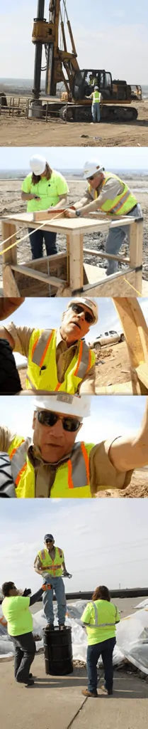
METHODOLOGY FOR ASSESSING MUNICIPAL SOLID WASTE USING A LARGE-DIAMETER BOREHOLE
LTC John F. Hartwell, Ph.D., P.E.
University of Nebraska, 2015
Municipal solid waste (MSW) landfills are permanent repositories of society’s non-hazardous wastes. Landfill facilities are becoming harder to site, resulting in increasing pressure to maximize the use of available airspace. Increasingly, this results in developing additional airspace by way of vertical expansion. This expansion imparts greater stress on the landfill mass and the containment infrastructure.
The engineer’s understanding of the geotechnical properties of MSW has been limited to sampling of relatively shallow test pits and reconstitution of disturbed MSW samples in the laboratory. Deeper assessment using small diameter borings is difficult and produces poor low volume samples for ex-situ testing. Some researchers have synthesized MSW with obvious limitations. Landfill failures have provided opportunities for back calculation of MSW properties including shear strength, but these estimates are based on limited understanding of unit weight and moisture content with depth.
The recent trend for the harvesting of methane produced by the anaerobic degradation of MSW has resulted in the need for nearly full-depth, large-diameter, landfill gas collection wells. Prior to completion, these boreholes provide excellent opportunities for directly observing and measuring the condition of MSW in its buried, variably degraded state at depths that are far greater than previously accessible.
The large diameter MSW gas well borehole assessment methodology presented in this paper is shown to be an efficient and valuable means for characterizing MSW. This means that the cost of the assessment is relatively low as the drilling costs are negligible and therefore limited to the cost of labor to sample and perform field observation and laboratory testing. The assessment methodology, which includes scaled full coverage photography and videography, allows precise analysis of a number of geotechnical properties such as wet and dry unit weight, moisture content, specific gravity, void ratio, % saturation of MSW and buried soil layers throughout the depth of the borehole. Further, MSW constituents and biologic degradation can be measured. The orientation / alignment of tensile reinforcement within the waste mass is readily observable. Zones of perched leachate and the effects of mechanical creep on borehole diameter can also be measured.
Contact John Hartwell or Contact SCS Engineers
Learn more about MSW Landfill Services from SCS.
Corporate Headquarters