
In our newest SCS Advice from the Field, Ali Khatami makes his case for the landfill chevron pattern…
For at least the past 50 years, our industry has referred to the design pattern for the bottom of landfill cells as herringbone. But, it’s time to break the long-standing herringbone reign and give credit to the true holder of the crown: the chevron pattern. A chevron pattern visualizes the actual geometry used by landfill designers over the decades.
The schematic views of both patterns are shown below:
![]()
Now, here’s a sketch of a landfill single-cell design:
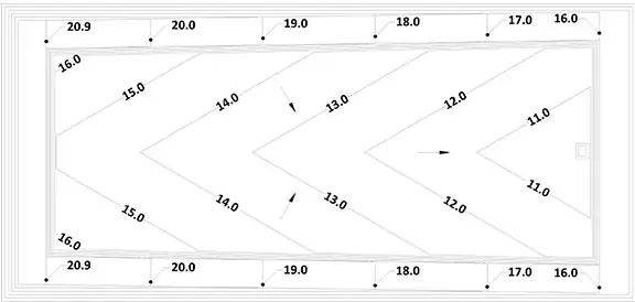
Note the cell base area with elevation contours that resemble the chevron pattern, with the leachate collection pipe located along the centerline of the cell. The cell base area is sloping toward the leachate collection pipe to convey landfill leachate at the base to the pipe, then the pipe conveys the leachate to the leachate sump located at the low end of the pipe. The pattern at the base can easily be duplicated in either direction of the cell area, developing a multi-cell design resembling the chevron pattern shown above.
In this case, the straight lines connect the low points (representing leachate collection pipes) and the high points (representing the divider berms separating adjacent cells). The zig-zag lines in the pattern remind landfill engineers of the elevation contours for the landfill bottom design geometry.
Meanwhile, with the herringbone pattern, the adjacent “tiles” or rectangular shapes are in a perpendicular position to each other and do not resemble the zig-zag lines in the chevron pattern. The herringbone pattern cannot be representative of the elevation contours, leachate collection pipes, and the boundary lines between adjacent cells like the chevron pattern. Additionally, the angle of line segments in the zig-zag in the chevron pattern can vary to any desirable value, which allows representation of changes to the disposal cell base slope (an important parameter in landfill design). On the contrary, the tile position in the herringbone pattern has to maintain perpendicular angles throughout and therefore it loses the ability to represent various base slopes.
One may draw lines along interface boundaries of the herringbone features and come up with the chevron pattern. But why stretch the truth when the chevron is already clearly the pattern? It is not apparent how or why the herringbone association took hold in the first place, but it’s about time that changed.
Admittedly, it took nearly four years to scientifically support the validity of the Special Relativity Theory from the time it was published by Albert Einstein in 1916. And it took nearly 50 years to physically detect the existence of Higgs boson particle from the time it was theorized by Peter Higgs in 1964. So, I suppose we can wait for formal recognition of chevron designation for landfill design.
Why such a big deal!?
The chevron validation may be insignificant compared to the scientific validations of Einstein’s and Higgs’ work. For landfill engineers, attune to details, it could be considered big because anything new, and more accurate in the landfill design field is a cheering matter!
Throughout the history of science, new findings supported by scientific evidence have replaced prior theories or concepts when progress is desired. Change of the pattern association, in this case, may not qualify as a scientific finding; however, it is a clear and noteworthy correction to what landfill engineers have been using over the past many years.
About the Author:
 Ali Khatami, Ph.D., PE, LEP, CGC, is a Project Director and a Vice President of SCS Engineers. He is also our National Expert for Landfill Design, Construction Quality Assurance, and Elevated Temperature Landfills. He has over 40 years of research and professional experience in mechanical, structural, and civil engineering.
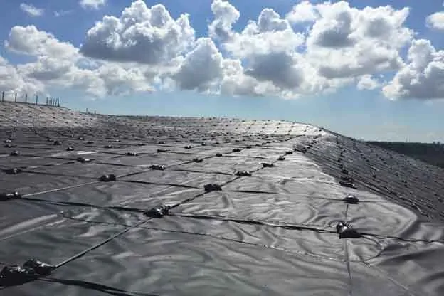
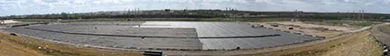
Landfill slopes that have reached final grades, or will receive waste in the distant future have maintenance challenges. Environmental elements continually affect surface conditions, and remedial work is required routinely to prevent negative outcomes of exposed slopes. Consider using a geomembrane temporary cap to address much of the maintenance. Here’s a list showing how the cap can help:
Landfill Maintenance Challenge
With Geomembrane Temporary Cap
The significant maintenance savings by using a temporary cap make the payoff period for the investment attractive. Based on my experience and site variations, the return on investment is usually three to six years. The period is considerably shorter if your landfill does not have a leachate disposal or treatment system, or deep injection well. The difference is the high cost to have the leachate hauled away.
Temporary caps potentially reduce routine maintenance work, leaving operation staff available for other tasks. The cap provides peace of mind that slopes remain in compliance; regulators don’t need to report non-compliance conditions of exposed slopes during inspection events.
After completing 25 temporary cap projects in the U.S. Southeast alone, we highly recommend using a thick geomembrane. It’s tempting to try to save money using a thinner geomembrane, such as 12 mils or 20 mils, but these can damage more easily and will negatively affect your return. The majority of SCS clients chose to use the recommended 40 mils thick geomembrane, which will survive severe weather conditions.
Ballasting the geomembrane and using the right materials for ballasting is significantly important. We recommend using ultraviolet (UV) resistant rope and sandbags, a tried and true system. UV resistant straps are a decent replacement for ropes. Anchoring mechanisms are also important. We typically recommend using 4×4 treated wood posts at 10-ft spacing, installed in anchor trenches, and tied to ballasting ropes. Depending on the site and operator’s preference, the supporting architecture may be to lay the post horizontally, while tied to the ballasting ropes, at the bottom of the anchor trench buried in the anchor trench’s backfill material.
Over the years, landfill operators have experienced the savings and value that temporary caps bring to landfill operating budgets, and we’re placing more temporary caps every year. If considering this option, SCS can assist you by evaluating the slopes at your site for the caps. We’ll also prepare estimates for the purchase of material and installation costs and estimated time of recovery for your project.
About the Author: Ali Khatami, Ph.D., PE, LEP, CGC, is a Project Director and a Vice President of SCS Engineers. He is also our National Expert for Elevated Temperature Landfills, plus Landfill Design and Construction Quality Assurance. He has nearly 40 years of research and professional experience in mechanical, structural, and civil engineering.
Learn more at Landfill Engineering
Welcome to the SCS Advice from the Field blog series.
Airspace is a golden egg, the equivalent to cash that a waste operating company will have overtime in its account. With each ton or cubic yard of waste received at the landfill, the non-monetary asset of airspace converts positively to the bottom line of the waste operating company’s books.
The larger the airspace, the larger the non-monetary asset, and the larger future cash potential in the account.
Therefore, it is extremely important to design landfill footprints optimally in consideration of planned operations at the site, and design landfill features maximizing airspace within the selected landfill footprint.
Optimization takes into consideration the land available for development, including the various facilities and systems necessary for operations. The type of design, depth of landfill, base slopes, leachate collection pipe slope, perimeter berm geometry and size, slopes of landfill side slopes, terraces on slopes, and many other parameters determine the airspace volume available to the landfill operator. The designer’s goal is to provide the most volume to the landfill operator.
How does the operator know that a proposed design is maximizing airspace?
If SCS is the site designer, the maximization of airspace is inherent in proposed designs for permitting. On numerous occasions, when SCS is not the site engineer, our designers have proposed a re-design of landfill features to maximize the airspace within its permitted footprint. Under these circumstances, it is not easy to convince a landfill operator of the benefits of SCS’s proposal. Naturally, one assumes a designer would not propose a lesser design on paper and carry it through the high cost of permitting, so it is common for the landfill operator to express doubts about our proposed changes. Once the operator and SCS review the technical design changes in detail, the demonstrated value becomes apparent. It is not a simple process, but on every occasion, we have successfully increased the airspace for the client, increasing potential revenue for millions of dollars beyond the originally permitted amounts.
Driven by the success of our clients, it is our culture to serve our clients completely as trusted professionals making your challenges our own. SCS is proud to say that at the date of this publication, our designers have created over $400,000,000 of additional financial benefit out of thin air for clients at a dozen landfills with more efficient landfill base grades that maximize airspace and cost less to construct.
As we move toward our 50th year, we hope to continually improve, evolve, and strive to maximize airspace at more landfills, adding value to our clients’ bottom line. Contact our nearest office if you are interested in a landfill evaluation for maximizing airspace and reducing construction costs. As always, our SCS authors are available to answer your questions or comments.
About the Author: Ali Khatami, Ph.D., PE, LEP, CGC, is a Project Director and a Vice President of SCS Engineers. He is also our National Expert for Landfill Design and Construction Quality Assurance. He has nearly 40 years of research and professional experience in mechanical, structural, and civil engineering.
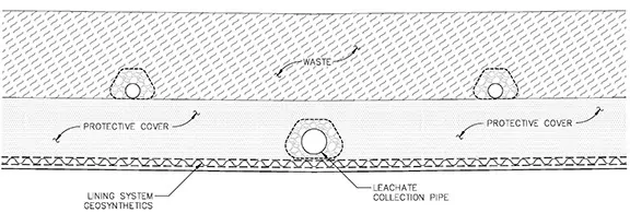
Gas production during the active life of landfills is a well-known phenomenon, with many means to collect and dispose of landfill gas already developed and implemented in landfills across the world. What is less known in the industry is that concentration of landfill gas near the lining system can reach significant levels, causing high gas pressure developing in, and around, the leachate collection drainage layer. High-pressure gas can potentially fill voids within the drainage layer (geocomposite or sand), causing conditions impeding flow in the drainage layer, adversely affecting the free flow of leachate.
Leachate collection pipes encased in gravel are pervious media through which landfill gas can easily travel and high pressures transfer to the sump area. Such conditions can cause significant odors near the sump due to emissions of landfill gas through the drainage layer and the overlying sand layer on the side slope of the perimeter berm near the sump. In addition, high-pressure builds in the riser and cleanout pipes.
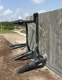
Consider an effective gas pressure removal system in the sump by installing vertical pipes on the riser pipes behind structures, on top of the perimeter berm, shown here. The vertical pipes are blind-flanged initially at cell construction completion. If the gas pressure build-up becomes significant, or odors are detected in the sump area, the landfill operator connects the vertical pipes to a vacuum source near the sump.
Using a connecting pipe to a vacuum source can also be used to discharge condensate from the gas collection and control system directly into the leachate collection riser pipe.
For a double lining system, with a riser pipe in the primary system and another in the secondary system, both risers will have vertical pipes on them, and both connected to the vacuum source.
However, condensate flowing down the connecting pipe from higher elevations toward the risers should not enter the secondary system. Block it by using a manifold, as shown in the image.
Operators may have a vertical pipe installed on the leachate collection pipe cleanout to apply vacuum directly to the leachate collection pipe.
Keeping gas pressure low in and around the leachate collection pipe promotes the free flow of leachate through the geocomposite or granular medium drainage layer to the leachate collection pipe, and improves leachate removal from the disposal cell.
Using gas removal piping at leachate sumps is highly recommended for warm or elevated temperature landfills where efficient leachate removal from the leachate collection system is another means for controlling landfill temperatures.
About the Author: Ali Khatami, Ph.D., PE, LEP, CGC, is a Project Director and a Vice President of SCS Engineers. He is also our National Expert for Landfill Design and Construction Quality Assurance. He has nearly 40 years of research and professional experience in mechanical, structural, and civil engineering.
Learn more at Landfill Engineering and Leachate Management
Landfill operators may add a casing pipe to their leachate force main for additional environmental protection. Consequently, the leachate force main is entirely located inside a casing pipe where the leachate force main is below ground. In the event of a leak from the leachate force main, liquids stay inside the casing pipe preventing leakage into the ground. During monitoring, checking for the presence of leachate inside of the casing pipes is routine.
For many years, I designed the installation of an HDPE monitoring manhole at each leachate removal sump station. Designed at the top of the perimeter berm, where the leachate force main is normally located, these manholes normally remain dry. The leachate force main crosses through the manhole without discharging into it. The casing pipes connecting to the manholes are open-ended at the manhole, draining directly into it. Easy to monitor, if liquids are present, you probably have a leak.
Using field operations experience, we improved the design.
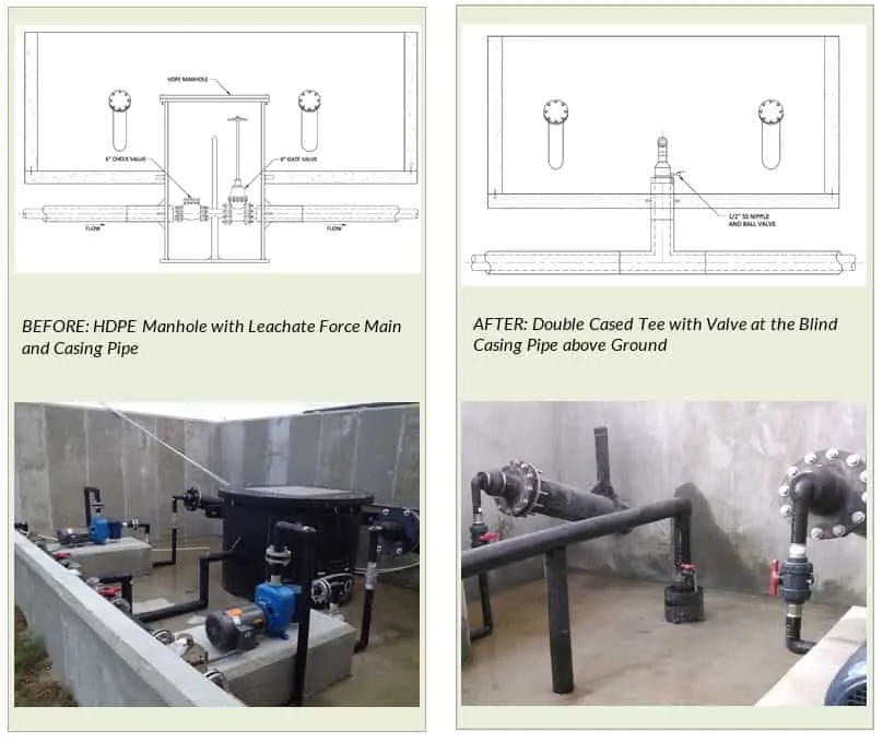
A blind casing pipe above the surface leaves the leachate line exposed for piping purposes. In this design, the casing pipe does not connect to any vessel for monitoring; instead, it has a pressure gauge or small valve on it for pressure monitoring.
If the gauge reads pressure in the casing pipe, it is indicating there is liquid inside the casing pipe; leachate is leaking from the force main and filling the casing pipe causing the pressure to build. If using a valve, monitoring is opening the valve to look for liquid coming out of the casing pipe. Regularly monitored pressure gauges or valves is a standard operating procedure and easily accomplished.
Pressure Release System Near Bottom of Landfills – Essential Component for Proper Functioning of the Landfill Drainage Layer
Landfill designers are generally diligent in performing extensive leachate head analysis for the design of the geocomposite drainage layer above the bottom geomembrane barrier layer. They perform HELP model analyses considering numerous scenarios to satisfy all requirements of the regulatory agency reviewing their work.
It’s great that the practice of landfill design is widespread and there are many solid waste professionals in the industry who can perform all sorts of analyses. However, there is a need for special attention to an operator’s observations in the field, sometimes lost in the course of communications. Unless one works in an organization with field services or closely coordinates the design with field operations personnel, some strategic considerations are never incorporated into the best design.
One phenomenon that solid waste designers may not be aware of is that significant landfill gas may accumulate near the bottom lining system and cause pressure build-up in and around the bottom lining system during waste filling operations. Fresh waste placed in a newly constructed disposal cell generates a significant amount of gas due to the presence of high levels of oxygen in the fresh waste lift. High levels of oxygen cause aerobic decomposition of waste with significant gas generating capacity.
High gas pressure builds near the leachate collection system means high gas pressure in the voids of the sand/soil layer above the geocomposite drainage layer, and the geocomposite pores. High gas pressure within the geocomposite can adversely affect the free flow of leachate through the geocomposite to the leachate collection pipe. This phenomenon can potentially cause a significant increase of leachate head within the geocomposite drainage layer, and even potentially cause saturation of the overlying sand/soil layer in some cases.
Address this situation by including a pressure release system in the design of the lining system. The pressure release system is a simple system including perforated HDPE pipes placed in parallel position at a certain spacing above the sand/soil layer in the longitudinal direction of the disposal cell extending from the perimeter berm, at the low end of the disposal cell, to the high end of the cell. The pressure release pipes extend to the top of the perimeter berm at the low end of the disposal cell and terminated by blind flanges. When pressure builds in the cell near the lining system, these pipes, connected to a vacuum source in the vicinity, remove the excess gas pressure from the bottom of the landfill.
The spacing of the pipes in the pressure release system and the design of the pipe bedding material are up to the designer. Such a system can be beneficial in removing gas pressure near the lining system throughout the life of the landfill, allowing the geocomposite drainage layer to function as intended in the design of the facility.
I have observed numerous cases of leachate not percolating through the geocomposite, that for any number of reasons was exposed during construction activities, simply due to excess gas pressure near the landfill lining system. I have also observed distorting of blind flanges at the end of the cleanout pipes due to high-pressure build-up near the lining system. Including a pressure release system for a nominal cost in your design can prevent the drainage layer, a major investment in the construction of the landfill, to function properly and maintain the leachate head within the range of the design parameters.
Based on my experience, I believe that solid waste designers dealing with warm landfills that fall into the category of potential future elevated temperature landfills, where removal of leachate in a very effective manner from the landfill is essential, should seriously consider a pressure release system above the bottom lining system for proper functioning of the drainage layer.
The author, Ali Khatami, Ph.D., P.E., has experienced very satisfactory performance results from the design.
Liquids Management and Landfill Design
The complexity of regulations that govern the disposal of coal combustion residuals (CCR) is growing. We expect the pace of change will also increase based on recent headlines. To help you successfully address these ever-changing regulations and stay focused on serving your customers, SCS Engineers uses our Advice From the Field blog and Technical Bulletins.
Using the SCS Advice blog we recently posted a short overview of the WIIN Act and highlights of how the Act is being received. This is just the start. In the coming weeks and months, SCS Engineers’ staff will bring you timely, relevant updates and interpretations of the WIIN Act and other changing regulations. Most importantly, we’ll recommend what to do next, steps you should consider taking and when to take them so that you’re ready for whatever changes come.
Follow the SCS blog on LinkedIn or Facebook for the latest information about coal combustion residuals regulations, and to participate in the conversation that’s shaping our industry. Or contact us at if you have questions.
SCS periodically prepares Technical Bulletins to highlight items of interest to our clients and friends. These are published on our website. For example, this SCS Technical Bulletin addresses Inactive Surface Impoundments and EPA Direct Final Rules for Disposal of Coal Combustion Residuals from Electric Utilities.
About Eric Nelson, SCS Engineers CCR National Expert
Question: I have a small oxidation event at my landfill and am continually testing for carbon monoxide (CO) in the surrounding landfill gas (LFG) extraction wells. Using colorimetric tubes, I am monitoring the readings which range from 5-10 parts per million (ppm). Is there an accepted standard for background carbon monoxide in LFG? Moreover, how much inaccuracy is expected using the colorimetric tube testing?
Answer: Carbon monoxide (CO) can be found in small quantities even when there is no landfill fire. If your concern is landfill fire, most reputable resources state that a landfill fire generates readings of at least 100 ppm CO and more typically in the 500-1000 ppm range with 1000 ppm a reliable indicator that a landfill fire event may be present.
CO readings on colorimetric tubes are inherently less accurate and tend to run higher than laboratory results. Colorimetric tubes do provide value as a real-time indicator versus subsequent lab results, and can be used as an index reading, calibrated by lab results later. If you’ve had a landfill fire event before, with CO levels greater than 100 ppm, the lab confirmed 5-10 ppm CO could be residual left over from the earlier event.
Although some people believe that the presence of CO at almost any level is an indicator of landfill fire, recent laboratory tests show that CO can be generated at values up to and over 1000 ppm by elevating refuse temperatures without the presence of combustion (fire). Other tests have shown that high values of CO are found in some landfills with no current landfill fire and no indication of a past landfill fire. This information supports that it is possible that Elevated Temperature (ET) Landfills can have CO levels over 1000 ppm CO without the presence of combustion or landfill fire.
In the end, CO can be an indicator of landfill fire, but not always, as described here. Low methane, high carbon dioxide, and even landfill temperatures above 131 degrees F may or may not be indicators of past or current landfill fire. Physical indicators of a landfill fire may include rapid settlement in a localized area, cracks and fissures, smoke and flame, melted landfill gas system components, and char on the inside of LFG headers and blower/flare station components such as a flame arrester. However, most of these indicators can occur at ET landfills as well without the presence of fire or combustion.
A professional landfill gas engineer is needed to assess these conditions as a whole, and make a judgment on the underlying driver, condition, and resolution.
Have a question for our SCS Professional Engineers or Field Staff? Just ask here.
Landfill and Landfill Gas Services at SCS Engineers.
Corporate Headquarters