Many environmental projects assume an unconfined aquifer groundwater gradient with a simple arrow and without performing an analysis of the validity of the underlying data and conclusions. Therefore it’s no surprise when deficiencies begin to occur in the project’s outcome.
Your client wants a commercial building installed. The construction seems straightforward, so a quick geotechnical investigation is conducted. The underlying shale is deemed dry after a brief period of well observations did not indicate groundwater was present.
Months later, groundwater problems start to manifest. Seepage at the foundation margins begins occurring. Uplift cracks develop as increasing groundwater pressure is exerted. From where is the groundwater coming; after all, your geotechnical investigation showed the underlying geology was dry.
It turns out that insufficient time was allowed to observe groundwater behavior in the shale. The groundwater was there all the time, but it moves so slowly through the shale that it did not have time to move into the wells that were constructed to check for groundwater. If the wells were left for a longer period—or some other means of checking for groundwater was employed—then the building foundation could have been more adequately designed for the groundwater conditions.
Groundwater gradient is like the sun rising: it’s always assumed and often does not get any real scrutiny in a typical project. However, there are several common scenarios in which basic assumptions about groundwater gradient and the velocity may lead to project design and outcome flaws such as unexpected uplift forces.
Groundwater Gradient and Topography
Groundwater gradient is assumed to be a subdued model of topography. How many times have you heard that? This assumption appears in the majority of environmental project site assessments. However, which topography is referenced? What scale is assumed?
The series of figures here show the problem with assuming gradient is directly tied to topography.
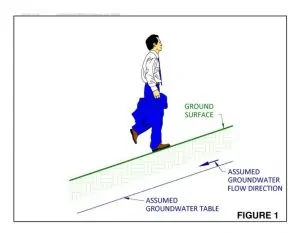
In Figure 1, the ground slope clearly implies a direction of flow—right? That implied direction of flow is illustrated.
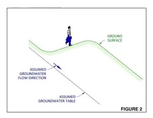 Figure 2 steps us back a bit in scale. Ah, the topography is reversed at this scale, meaning that our first assumption regarding groundwater flow direction appears to be way off.
Will adding a new, presumed flow direction correct the issue? Not always.
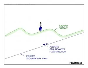
Figure 3 steps back further and shows another topographic reversal and reversed groundwater flow direction. The point is, topography may by no means be a reliable indicator of groundwater flow—it depends on scale. Although the topographic reversals illustrated in Figure 3 seem uncommon, they are vertically exaggerated illustrating that topographic reversals at various scales are the norm.
Groundwater Gradient in Low-Permeability Formations
Groundwater gradient in low permeability formations can be quite deceiving. Erroneous assumptions can be caused by (1) a misunderstanding regarding the hydraulic connectedness between points used to develop a presumed water surface, and (2) extremely slow hydraulic response in a measurement point [well], which may cause water level measurements that are not in equilibrium with the formation water pressure. Let’s explore each of these two items:
Are your groundwater measuring points hydraulically connected? This is often a prima facie assumption that goes without any scrutiny in a site analysis. Water table elevation lines are smoothly drawn between measurements points [wells], implying that any hypothetical well that may be installed in between will indicate a water level consistent with the interpolation. The assumption is certainly valid in textbook illustrations, but the reality of low or varying hydraulic conductivity could create water table variations that differ widely from a simple interpolation between measurement points. It is even possible that a formation is dry between measurement points (see below).
An extremely slow hydraulic response may result in erroneous (premature) interpretations of water level/water pressure in a formation. A well installed in shale may require months or even years to indicate a water level that is in equilibrium with the formation. Consequently, a well reportedly installed in dry shale may not be dry at all—the shale may have considerable pore pressure that just requires substantial time to manifest itself in a well. One solution to this problem if these data must be obtained quickly is to substitute an instant-reading pore pressure transducer instead of a well.
Groundwater Gradient in Urban Environments
 Assuming topography is the dominant control on groundwater gradient in urban environments can be risky. Groundwater gradient in urban environments can be especially flat relative to rural areas because anthropogenic improvements to land often result in flattening the ground surface. This often results in a general flattening of the water table surface, and a lack of a corresponding strong or consistent gradient that would drive flow.
Another often-neglected aspect of the urban environment is the effect of paving. Many urban areas feature vast paved areas that prevent groundwater recharge and cause a recharge shadow that may result in an inward gradient that is in most cases distinctly different from what little topographic gradient may exist after construction.
Urban groundwater movement is often more affected by subsurface (i.e., invisible) non-topographic, anthropomorphic features. Features such as leaking pipelines and tanks may cause hidden recharge that affects gradient. Construction activities also often result in preferred pathways or conduits for groundwater flow. Again, most of these artificial subsurface flow conduits are usually hidden. The result is a complex flow regime that does anything but mimic topography.
The Role of Groundwater Velocity
Groundwater velocity is similarly neglected in many project considerations. Assuming groundwater gradient is known accurately, is it important? If the gradient is very flat, the velocity may be insignificant. A flat gradient may be prone to shifting directions, subtly driving a flow gradient in various directions. Project assumptions often include an explicit reference to upgradient and downgradient that may be misleading because the degree or relative flatness and corresponding low velocity may dictate that upgradient vs. downgradient is poorly defined. In this situation, conclusions should not be hastily drawn regarding the apparent impacts of a source that is apparently upgradient.
Best Practices in the Face of Groundwater Gradient, Flow and Velocity Uncertainty
First, acknowledge the uncertainty and address it in your project. Don’t instantly dismiss gradient with a wave of the hand and a simple statement about gradient mimicking topography.
When groundwater gradient is critical to a project design or outcome, it should be directly and carefully measured. Wells or piezometers have to be carefully designed, installed, and surveyed for elevation. Water level measurements must similarly be done with appropriate consideration of the factors noted above.
If you are working in a low-permeability formation, consider the outcome if your measuring points are not hydraulically connected, and therefore cannot be used to map an apparent water surface. If your measuring points are implying a continuous water surface and connected flow regime that does not exist, consider this potential on your project design and outcome.
About Jim Lawrence
Mr. Lawrence is a hydrogeologist with 30 years of expertise in all aspects of hydrogeology and geology. Mr. Lawrence leads the SCS Engineers – Texas solid waste landfill groundwater monitoring programs for clients. He works to resolve problems that arise with groundwater monitoring, including assessment monitoring, corrective action, landfill gas, and alternate source demonstration issues. He is responsible for supervising the sampling, data reporting, and statistical analysis for numerous municipal solid waste landfills and clients in other industries. His job experience includes extensive permitting-related hydrogeologic characterizations of project sites.
Corporate Headquarters