Pressure Release System Near Bottom of Landfills – Essential Component for Proper Functioning of the Landfill Drainage Layer
Landfill designers are generally diligent in performing extensive leachate head analysis for the design of the geocomposite drainage layer above the bottom geomembrane barrier layer. They perform HELP model analyses considering numerous scenarios to satisfy all requirements of the regulatory agency reviewing their work.
It’s great that the practice of landfill design is widespread and there are many solid waste professionals in the industry who can perform all sorts of analyses. However, there is a need for special attention to an operator’s observations in the field, sometimes lost in the course of communications. Unless one works in an organization with field services or closely coordinates the design with field operations personnel, some strategic considerations are never incorporated into the best design.
One phenomenon that solid waste designers may not be aware of is that significant landfill gas may accumulate near the bottom lining system and cause pressure build-up in and around the bottom lining system during waste filling operations. Fresh waste placed in a newly constructed disposal cell generates a significant amount of gas due to the presence of high levels of oxygen in the fresh waste lift. High levels of oxygen cause aerobic decomposition of waste with significant gas generating capacity.
High gas pressure builds near the leachate collection system means high gas pressure in the voids of the sand/soil layer above the geocomposite drainage layer, and the geocomposite pores. High gas pressure within the geocomposite can adversely affect the free flow of leachate through the geocomposite to the leachate collection pipe. This phenomenon can potentially cause a significant increase of leachate head within the geocomposite drainage layer, and even potentially cause saturation of the overlying sand/soil layer in some cases.
Address this situation by including a pressure release system in the design of the lining system. The pressure release system is a simple system including perforated HDPE pipes placed in parallel position at a certain spacing above the sand/soil layer in the longitudinal direction of the disposal cell extending from the perimeter berm, at the low end of the disposal cell, to the high end of the cell. The pressure release pipes extend to the top of the perimeter berm at the low end of the disposal cell and terminated by blind flanges. When pressure builds in the cell near the lining system, these pipes, connected to a vacuum source in the vicinity, remove the excess gas pressure from the bottom of the landfill.
The spacing of the pipes in the pressure release system and the design of the pipe bedding material are up to the designer. Such a system can be beneficial in removing gas pressure near the lining system throughout the life of the landfill, allowing the geocomposite drainage layer to function as intended in the design of the facility.
I have observed numerous cases of leachate not percolating through the geocomposite, that for any number of reasons was exposed during construction activities, simply due to excess gas pressure near the landfill lining system. I have also observed distorting of blind flanges at the end of the cleanout pipes due to high-pressure build-up near the lining system. Including a pressure release system for a nominal cost in your design can prevent the drainage layer, a major investment in the construction of the landfill, to function properly and maintain the leachate head within the range of the design parameters.
Based on my experience, I believe that solid waste designers dealing with warm landfills that fall into the category of potential future elevated temperature landfills, where removal of leachate in a very effective manner from the landfill is essential, should seriously consider a pressure release system above the bottom lining system for proper functioning of the drainage layer.
 The author, Ali Khatami, Ph.D., P.E., has experienced very satisfactory performance results from the design.
Liquids Management and Landfill Design
Another in the series, SCS Advice from the Field. It is possible to simplify landfill maintenance and create air space.
Many landfill designers continue to incorporate terraces on the outside slopes of landfills, but not always for sound reasons. Sometimes, terraces are necessary to maintain landfill slopes in stable condition, due to the low shear strength of the foundation soils, or when required according to the specific state or local solid waste rules.
At times designers propose terraces on slopes to collect and convey surface water runoff from a landfill’s higher slopes to a low point on the terrace where the downchute system is located. On paper, it’s easy to show nicely sloping terraces toward a low point, with transverse slopes toward the landfill slope, to control surface water. However, terraces cause significant operational issues for landfill operators. Some of these problems are very apparent, and some realized when a portion of the landfill slope is scheduled to receive a permanent final cover.
Consider these factors during permitting and design, as follows:
It is difficult to shape sloping terraces during waste placement operations; terraces can end up formed horizontally. When it is time to close the landfill’s side slope, significant amounts of soil are placed along the terrace to make it slope toward a low point where the downchute system is located. Normally, permit drawings do not include sufficient details to illustrate these technical issues, and the operator would not have the specific knowledge of such issues at the time of closing the slope.
During waste placement, difficulties arise for the equipment operator (dozer pushing waste and compactor compacting and shaping surfaces) to shape the breaklines and compress waste properly to form the terrace. Lack of compaction near the outside breakline of the terrace makes it susceptible to excessive settlement and can cause the terrace to change shape over time.
Operators shape the transverse slope of the terrace either horizontally, or sloping away from the landfill slope to manage surface water during the landfill’s operational phase. In either case, the slopes could end up formed differently, or in the opposite direction of the slopes in the permit drawings. Closure of the landfill slope requires special attention along with large quantities of soil to shape the terrace similar to what is in the permit drawings. Again, the landfill operator would not know of the additional work and the soil quantities necessary to fix the terrace transverse slope properly.
Settlement in waste causes previously shaped terraces, at a certain elevation ending up lower than the originally shaped terraces. Over time, the terrace originally constructed at a certain elevation and following the permit documents ends up lower in elevation due to waste settlement. Continuously occurring settlement can cause the misalignment of terraces formed at different intervals. At the time of closing, the terrace misalignments become a major problem for the engineer and contractor to meet elevations and shapes previously permitted.
Downchute pipes extend from the highest terrace to the lowest terrace and the surface water management system at the perimeter of the landfill. The downchute pipes are designed to cross the width of each terrace and pickup surface water from each terrace. However, the pipe design is complicated by the terrace transverse slopes toward the landfill slope causes construction complications and increasing the risk of failing to properly collect surface waters at the low point. This particular risk can become drastic when considering waste settlement changing the surface geometry at the inlets to the downchute system, causing costly repairs.
Over the terrace surface, the geocomposite drainage layer in the final cover follows the transverse slope toward the landfill slope and across the width of the terrace. Water in the geocomposite from the higher slope and water from the terrace reach the inside edge of the terrace, with nowhere to go except to follow the longitudinal slope of the terrace along the interior edge. Geocomposite is not designed to carry such a large quantity of water along the interior edge for the entire length of the terrace. Inevitably, problems arise, and potential failures can occur along the terrace. The solution is to install a toe drain along the interior edge of the terrace that collects and conveys water in the geocomposite layer to the low point in the terrace. This toe drain adds another complication to the design of the piping system at the low point of the terrace, where the down chute system is located. Additionally, the cost of the toe drain construction goes up significantly due to logistical complications during construction of the toe drain along the terrace in the middle of the slope-, including the placement of gravel around the toe drain pipe before the geomembrane and geocomposite are covered with the overlying soil.
The access road, to the top of the landfill, normally crosses several terraces located on the landfill slope. The slope surface geometry at the intersection of the access road with the terraces becomes complicated, affecting the alignment of the access road at each intersection point.
Leachate seeps can potentially appear at breaklines on landfill slopes. The inside edges of a terrace are considered breaklines in the landfill slope and are highly susceptible to leachate seeps appearing on the surface. It is common to observe leachate seeps at terraces on landfill slopes. Unfortunately, leachate ponding on the terrace surface from the seeps can easily mix with surface water runoff on the terrace. It’s then carried to the landfill perimeter surface water management ditches and detention/retention areas.
Significant leachate seeps at terraces may require a leachate toe drain system below the final cover geomembrane along the entire length of the terrace; adding cost and another level of complication at the low point of the terrace where the downchute system is located. The leachate in the toe drain system needs to drain to another system at the low point of the terrace, to discharge to the landfill leachate collection system or another liquid management system.
To uncomplicated operations, more landfills are designed without terraces on the slope. Before slope closure management of the surface water runoff is achieved by temporary tack-on berms on the slope and temporary downchute pipes that are constructed and maintained easily. After closure the surface water management is achieved by permanent tack-on berms at certain spacing on the slope; berms are constructed as specified in the permit documents. The swale on the upper side of the tack-on berm conveys surface water runoff from the higher slopes to the low point of the swale on the slope.
The downchute system at the low point of the tack-on berms is simple to construct. These downchutes connect to lateral pipes from lower-level swales collecting surface water from these swales before discharging to the perimeter surface water management system. The aforementioned design does not require significant maintenance.
Maximizing Airspace
Terraces decrease potential airspace within the permitted footprint of the landfill. Wasted airspace on landfill slopes is substantial and can be in the order of tens of millions of dollars depending on the size of the landfill. Owners/Operators request airspace loss calculations to emphasize the financial impact of terraces on their bottom line.
One recent evaluation for a 170-acre, 250-ft tall landfill with seven terraces lost approximately 7,500,000 cubic yards of air space. The tipping fee of $80 per ton results in an estimated value of $64.00 per cubic yard of compacted waste. Therefore, the estimated value of the airspace loses due to the terraces at this landfill site is estimated to cost $480,000,000, nearly half-a-billion dollars of the bottom line.
This author, Ali Khatami, Ph.D., P.E. with SCS Engineers, has over 30 years of landfill design and construction for municipalities and private firms. He has first-hand knowledge of the satisfaction and cost-effectiveness of no-terrace systems by landfill operators he has worked with over three decades; many of whom changed their permits to eliminate terraces to take advantage of the airspace and operational benefits.
Ask our authors questions, by writing to or contacting Dr. Khatami directly.
Typical designs of landfill disposal cells include two slopes, one at the landfill base and the other along the leachate collection pipe. The drainage layer covering the entire cell base area follows the slope of the base toward the leachate collection pipe, and the flow in the leachate collection pipe follows the pipe slope. With the growth in the application of geosynthetics in the landfill industry, the majority of modern landfill designs include a geocomposite drainage layer, unless a granular material is readily available at an economically viable cost in the area of the landfill, which can replace the geocomposite material.
Base slopes are designed to maintain a positive flow toward the leachate collection pipe after long-term settlements of the foundation. In addition to this requirement, sometimes solid waste rules require either a minimum slope at the time of the design or a minimum slope after foundation settlement.
Regulatory agencies go through a comprehensive review process to make sure that such matters are addressed in a solid permit application involving the design of new disposal cells. However, sometimes designers propose slopes that seem to be significantly steeper than the minimum values required in the rules with no supporting foundation settlement analysis to justify the need for the steeper slopes. Slopes steeper than what is required (technically or regulatory-wise) have two drawbacks: 1) loss of the airspace which otherwise would be captured with a less steep slope; 2) lower liquid transmissivity in the geocomposite drainage layer. Laboratory experiments have shown that transmissivity of geocomposites reduces as gradient increases. This phenomenon may be related to higher turbulence in the flow of leachate through the geocomposite voids. The flow path of liquids within the geocomposite structure includes vertical and horizontal barriers that liquid flows around or over within the geocomposite thickness. Steeper slopes increase the velocity of liquids through the geocomposite, and higher velocity makes the flow more turbulent, and the higher turbulence reduces transmissivity.
One of the most important regulatory requirements on a landfill’s bottom lining system drainage layer is that the maximum head of leachate over the liner should not exceed 1 ft. When this requirement was developed, the consensus was that the drainage layer consisted of granular materials. Later, when geonets and geocomposites entered the market, the unwritten consensus among solid waste engineers and regulators was that the maximum head of leachate at the base should not exceed the thickness of the geonet or geocomposite drainage layer. With that in mind, the reduction in transmissivity of geocomposite laid over steeper slopes can adversely impact the maximum leachate head over the liner. Maximum leachate head is normally calculated from the theoretical model (along with some simplifications to disregard very small terms in the theoretical model) developed by C. A. Moore, J.P. Giroud, B. M. McEnroe, and others. One of these models was later incorporated into the Hydrologic Evaluation of Landfill Performance (HELP) model that is currently used by almost all solid waste engineers in the industry. Such model includes a parameter called hydraulic conductivity which is calculated from the transmissivity value of the geocomposite drainage layer. When transmissivity value reduces due to steeper slope at the base, the hydraulic conductivity reduces in turn as well. In the Moore’s and Giroud’s models, the maximum head of leachate is somewhat inversely proportional to the square roots of the hydraulic conductivity, which means the reducing hydraulic conductivity results in an increase in the maximum head of leachate passing through the geocomposite. The relationship between the leachate maximum head and the hydraulic conductivity is a lot more complicated in McEnroe’s model.
It’s recommended that the minimum base slope be initially determined based on foundation settlement. Then, the calculated minimum slope compared to the required value in the solid waste regulations, if any. If the rules require a minimum slope at the time of the design, pick the regulatory value if higher than the calculated minimum slope; otherwise, pick the calculated minimum slope. If the rules require a minimum slope after foundation settlement, then add the calculated minimum slope to the minimum slope in the rules and use that in the design.
A 1 percent slope at the base, provided all requirements are met, seems to be a suitable slope. The geocomposite transmissivity at 1 percent is higher than the transmissivity at 2 percent, and the space difference between the 1 percent and 2 percent slopes can be added to the landfill airspace for waste disposal.
Author: Ali Khatami, PhD, PE, LEP, CGC, is a Project Director and a Vice President of SCS Engineers. He is also our National Expert for Landfill Design and Construction Quality Assurance.
Landfill Design – Information and Case Studies
The drainage layers of landfill final covers normally go through a rigorous flow capacity evaluation. This evaluation is necessary to ensure that the volume of water reaching the drainage layer due to percolation of precipitation water through the final cover upper soil layer will not overwhelm the drainage layer in its flow path. If the flow volume in the geocomposite drainage layer is greater than the capacity of the drainage layer, water will exit the geocomposite and enter the overlying soil. The water entering the soil layer can easily saturate the lower portion of the soil layer, which will affect the stability of the slope. The geocomposite should always be designed to have a flow capacity greater than the flow rate of water running through it.
Concave areas of a landfill slope experience flow patterns quite different from slopes that go straight down. Slopes with concaved geometry have an unequal crest and toe lines – the toe line being smaller than the crest line. As a result, the width of the concaved slope decreases as the distance from the crest line increases in the downward direction. The narrowest width of the concaved slope is at the toe of the slope. The drainage layer on the slope experiences the same width change from the crest line to the toe line. This means that the overall width of the channels that carry water within the geocomposite drainage layer decreases toward the toe line, and, therefore, the depth of water in the channels increases. This phenomenon is referred to as flow convergence, and the convergence is toward the vertical centerline of the concaved slope. The flow convergence may be significant enough to increase the water depth in the geocomposite in the vicinity of the vertical centerline of the slope to greater than the thickness of the geocomposite. That, in turn, forces water out of the geocomposite and into the overlying soil, which may result in slope stability problems.
To complement the geocomposite flow capacity along the vertical centerline of the concaved slope in order to accommodate the higher water flow rates in the system, a pipe-gravel-geotextile (a burrito) may be constructed along the vertical centerline of the slope. The burrito, which would be positioned directly over the geocomposite drainage layer, increases the flow capacity of the system at and in the vicinity of the vertical centerline of the concaved slope. The burrito will receive water from the geocomposite where the water depth exceeds the geocomposite thickness. The burrito will be connected to the toe drain system at the toe of the slope, and water in the burrito will be discharged to the toe drain. The water in the toe drain, in turn, leaves the final cover through lateral drain pipes at regular intervals.
It should be noted that not every concaved slope requires a burrito. Some concaved slopes may be fairly wide, and the convergence of water inside the geocomposite may not be significant enough to cause the depth of water to exceed the geocomposite thickness. But, if the concavity of the slope is significant, a severe convergence of water in the geocomposite drainage layer is more likely. In that case, a burrito along the vertical centerline of the concaved slope is highly recommended.
A cautionary construction related note seems to be appropriate at this point. During construction, extra care should be taken to ensure that all geocomposite panels within the boundary of the concaved slope run such that the machine direction of the panels follows a path from the top toward the bottom of the slope. If some geocomposite panels are installed with the machine direction running across the slope width, significant turbulence in the flow will be created at the point where panels running in one direction transition to the panels running in the other direction. The turbulence will reduce the flow capacity of the geocomposite.
If you are planning to install a final cover over a portion of the slope that has concaved geometry and you want your final cover design to properly address flow volumes in the geocomposite drainage layer, please contact us. SCS Engineers has extensive experience with these types of circumstances, and we will gladly review your case and make recommendations. Learn more here.
If you have comments or questions about this article, please contact Dr. Ali Khatami.
Ali Khatami, Ph.D., PE, LEP, CGC, is a Project Director and a Vice President of SCS Engineers. He is also our National Expert for Landfill Design and Construction Quality Assurance. He has nearly 40 years of research and professional experience in mechanical, structural, and civil engineering.
Dr. Khatami has acquired extensive experience and knowledge in the areas of geology, hydrogeology, hydrology, hydraulics, construction methods, material science, construction quality assurance (CQA), and stability of earth systems. Dr. Khatami has applied this experience in the siting of numerous landfills and the remediation of hazardous waste contaminated sites.
Dr. Khatami has been involved in the design and permitting of civil and environmental projects such as surface water management systems, drainage structures, municipal solid waste landfills, hazardous solid waste landfills, low-level radioactive waste landfills, leachate and wastewater conveyance and treatment systems. He is also involved in the design of gas management systems, hazardous waste impoundments, storage tank systems, waste tire processing facilities, composting facilities, material recovery facilities, landfill gas collection and disposal systems, leachate evaporator systems, and liquid impoundment floating covers.
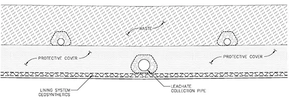
One general problem that is encountered in traditional designs is the potential for clogging of geotextiles in the vicinity of the leachate collection pipes.
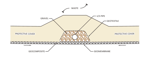
Traditionally, leachate collection pipes are encased in gravel, wrapped in geotextile, and positioned above the leachate collection system geocomposite drainage layer inside a trench or at the trough of the bottom of a cell. In a traditional design, leachate travels through the geonet component of the geocomposite and reaches the leachate trench where the leachate collection pipe is located. Here, leachate must flow out of the geocomposite, through the upper geotextile component, and then through the geotextile wrapped around the gravel, before entering the gravel and eventually flowing through the pipe. The flow through the geotextiles is concentrated in small areas on the two sides of the leachate collection pipe-gravel-geotextile wrap. Considering the large volume of leachate that follows this path over the life of the cell, it is evident why traditional designs are doomed to clog.
The clogging impedes the free flow of leachate from the geocomposite drainage layer to the leachate collection pipe. As the clogging occurs, the leachate must find a new flow path (most likely further back from the collection pipe), and flow out of the geocomposite, through the geotextile wrap at a different location, and eventually enter the gravel and pipe. This new location will eventually clog as well for the same reasons that the initial location was clogged. This process continues until the geotextile within the leachate trench becomes completely clogged and the system loses functionality. Unfortunately, the periodic cleaning of leachate collection pipes (usually every few years) cannot address this issue because the problem is outside the pipe and the high-pressure jets inside the pipes do not reach the clogged locations.
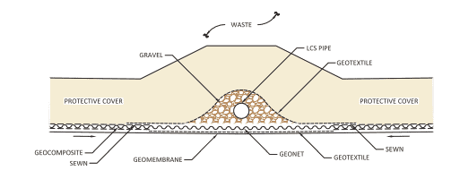
The solution is to eliminate geotextiles from the flow path of the leachate, extending from the geocomposite drainage layer to the leachate collection pipe. Over the past several years, SCS has successfully designed and constructed numerous landfill cells with no geotextile in the flow path of leachate from the geocomposite drainage layer to the leachate collection pipe. The design follows the “Rule of Transmissivities” which dictates that a proper design should provide the free flow of leachate from one medium to another and that only occurs when the transmissivity of the latter medium is equal to or greater than the transmissivity of the former medium. If a design does not satisfy the Rule of Transmissivities, there may be potential for clogging, bottlenecking of flow, and other consequences resulting from impeded flow in the system.
SCS Engineers is a leader in the design of landfill lining systems, and we have experience with issues that may not be familiar to other firms. If you are interested in the design of a leachate collection system at your facility, please contact SCS. Our professional engineers will gladly review your design and make recommendations if needed. We can identify potential issues and improve designs to prevent future problems and maintenance during the life of your facility.
Questions? Contact Ali Khatami, PhD, PE, LEP, CGC, is a Project Director and a Vice President of SCS Engineers. He is also our National Expert for Landfill Design and Construction Quality Assurance. He has nearly 40 years of research and professional experience in mechanical, structural, and civil engineering. Dr. Khatami has acquired extensive experience and knowledge in the areas of geology, hydrogeology, hydrology, hydraulics, construction methods, material science, construction quality assurance (CQA), and stability of earth systems. Dr. Khatami has applied this experience in the siting of numerous landfills and the remediation of hazardous waste contaminated sites.
Read more here. Rule of Transmissivities at Material Interfaces in Landfill Leachate Collection Systems, in Talking Trash
Corporate Headquarters