Lately, landfill operators are putting stock in onsite landfill leachate treatment systems as a strategy to stay on top of increasing requirements in their already demanding regulatory world. Leachate treatment systems help meet tightening restrictions on liquids that landfills send to municipal wastewater treatment plants or discharge directly. And onsite leachate treatment gives operators a leg up should they one day have to deal with any emerging contaminants found on an expanding list.
With their eyes on compliance, landfill owners and operators are looking to leachate treatment systems that can ease the impact of soaring leachate disposal costs. Of course, the more contamination, the harder the hit since higher contaminants can mean higher municipal treatment plant surcharges or the landfill having to haul its leachate longer distances to a treatment plant that will accept it. Both examples usually result in higher treatment, disposal, and hauling costs.
A spike in its ammonia concentrations was enough impetus for one Oregon landfill operator to turn to SCS Engineers a few months ago. At its highest levels, the ammonia climbed to 50-fold what many small wastewater treatment plants, like the one in the Northwest, will take over the long-term.
Project Director Shane Latimer and Technical Lead Sam Cooke got on the stick to figure out how their client could keep hauling and disposing of leachate at the local wastewater treatment plant it has routinely relied on for years.
Coming up with a plan is a complex, multi-step process that requires looking through many lenses. To design a cost-effective, efficient treatment facility, Latimer and Cooke use an in-house multidisciplinary team of co-workers from Project Management, Chemical Engineering, Civil Engineering, and Geotechnical Engineering. The team performs in-depth analyses to identify the most economical and feasible technology. A design that in this case not only addresses ammonia but prepares the operator for emerging contaminants, such as the possible need for per and polyfluoroalkyl substances (PFAS) reduction, which Cooke describes as a train that has not yet arrived in Oregon but has left the station and is heading down the track.
Starting with the most immediate concern, Cooke says, “Our client had seen ammonia concentrations between 500 and 1,500 mg per liter, which is high. Acceptable ammonia levels can vary depending on the type of facility and how much leachate they expect to get compared to their total flow. But small treatment plants like the one our client depends on will set ammonia limits of about 25 or 30 mg per liter,” he says.
SCS begins with a leachate pretreatment options analysis to dive into details beyond ammonia levels – spikes in ammonia call for close attention. Still, there’s more to consider in masterminding a robust and fitting plan to manage the complex process.
“These are biological treatment systems, and there is no one-size-fits-all answer. You need to know how these systems will react to whatever is in your leachate, so you have to account for more than ammonia, or whatever your constituents of concern are,” Latimer says.
SCS’s leachate contaminant analyses use the landfill’s historical data along with what they learn from tests that SCS orders to understand alkalinity, pH, and carbon, among other leachate chemistry puzzle pieces.
“We look at concentrations of raw leachate, flow rate, pretreatment requirements, and other factors. We want to get a comprehensive picture of the problem and ultimately make the best treatment decision to get compound concentrations down to acceptable discharge levels,” Latimer explains.
What customized solution did the team design for the client in Oregon? The system of choice is a membrane bioreactor (MBR), which combines membrane separation technology with traditional activated sludge technology with optional reverse osmosis treatment. The design is a compact, efficient, biological wastewater treatment plant.
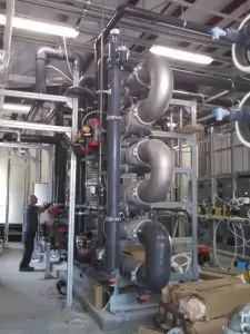
“An MBR is an elegant solution. We found it to be a good choice for this application for several reasons. It takes up relatively little space and fits well within the available plant footprint. It produces a relatively low-volume waste sludge stream. And it can cost-effectively treat multiple constituents of concern, so should new leachate chemistry issues arise, an MBR can address many of them,” Cooke says.
Being able to handle multiple concerns if and when they arise is key here. Cooke and Latimer wanted not only to get the immediate problem in check but see that the client has a dynamic and robust system to tackle whatever new challenges may be down the road.
When SCS goes into design mode, they plan ahead by engineering modular systems to add additional treatment methods if and when they’re necessary.
“For instance, MBR treats the leachate to reduce ammonia, other nutrients, organics, and suspended solids. By leveraging this treatment method first, you eliminate a lot of the bulkier constituents. But we left room for a modular addition such as reverse osmosis for “polishing,” treating MBR discharge for other minor constituents including PFAS,” Cooke says.
The client who came to SCS for a relatively inexpensive remedy for an ammonia problem now has a feasible, economical asset for leachate management.
“These investments are good security for landfill operators,” says Latimer. “If a municipal wastewater treatment plant is struggling to meet its standards, eliminating one contributing source of wastewater, like a landfill, could potentially solve several issues, such as ammonia, biochemical oxygen demand, and total suspended solids.”
But these treatment systems provide added security for more than the landfill.
“When disposal sites invest in sound leachate treatment systems, it’s also good for municipal wastewater treatment plants. It assures them that landfill operators will help them with the overall regulatory burden. We are helping them both to prepare for present and future challenges,” says Latimer.
Additional Resources:
Information, case studies, upcoming events
Landfill Leachate for Heavy Industry
SCS’s leachate management team is available to answer your questions on this blog or our other treatment designs at
SCS Engineers’ Gomathy Radhakrishna Iyer explains, “The structure of PFAs is a carbon and fluorine bond, and that bond is considered one of the strongest in nature. For industry, Chlorofluorocarbons (CFC), a volatile derivative of methane, ethane, and propane, creates problems globally after they’ve been released. Chlorofluorocarbons are strong greenhouse gases and are also responsible for the destruction of stratospheric ozone.
The most publicized of these compounds are those used as coolants in refrigeration and air conditioners, as propellants in spray cans and similar products, and as solvents for industrial purposes. Chlorofluorocarbons are far less abundant than carbon dioxide in the atmosphere. Still, they are 10,000 times more potent as a greenhouse gas and can remain in the atmosphere for more than 45 to 100 years. Reference
Iyer continues, “PFAS has the same kind of carbon-fluorine bond as CFC but linked to several C-F bonds like a chain making them even more inert and hard to degrade. Breaking this bond is what makes finding effective leachate treatments challenging, but certainly possible.”
It takes a savvy engineer to design safe and effective systems. We’re very proud of our Young Professionals like Gomathy – they’re smart and continue learning with the guidance of our VEPs – very experienced professionals.
Open positions at SCS Engineers for YPs and VEPs
Landfill operators have known about elevated temperature conditions in landfills for nearly a decade. Some operators have already incurred numerous expenses to control adverse environmental and operational issues at these landfills, and some operators have set aside large amounts of money in their books to address future liabilities associated with such landfills. Due to the complexities of controlling elevated temperature conditions and the compliance issues arising from such conditions, it can force operators to temporarily, or permanently close their landfills.
Can design address elevated temperature conditions?
The operators of larger landfills have been monitoring and analyzing data to identify triggering factors, while others continue controlling the environmental impacts. Environmental Research & Education Foundation (EREF) initiated several research projects to identify the triggering factors with the excellent scientific work of highly qualified researchers. These are on-going projects.
In the meanwhile, operators of larger landfills are developing strategies, basing strategic-decisions on the data and conditions collected during operations over long periods. After analyses, they have the means to reduce the impacts by making changes in their operations and landfill designs. The most effective changes include eliminating certain waste types from the waste stream and improving the movement of liquid and gas through the waste column with new designs.
Are design innovations consistently implemented?
The pioneering designs feature preventative measures, intending to avert the formation of elevated temperature conditions in future disposal cells. Implementing these new design features requires careful consideration and functional analyses, as some of the recommendations can be costly, affecting the bottom line. The urgency in controlling compliance issues associated with elevated temperatures and the associated financial impacts of such conditions objectively prescribe that local managers work closely with their designers and field expertise to bring non-compliance issues under control.
Is this an executive risk management strategy?
Until the on-going research more clearly identifies the triggering factors and the means to prevent the development of elevated temperature conditions, it seems logical to invest in implementing preventative measures that are currently available. When more research results are accessible, then the local managers will be able to make decisions that are even more informed. Those wanting to address the likelihood of future liabilities proactively will need executive-level funding and superior technical support, all of which are possible.
Is there much sharing of newer designs and strategies within the solid waste industry?
Yes, there is a fair amount of collaboration among the technical community and within solid waste associations. Most operators share their preventative designs within the engineering community and help contribute to funded research. Their actions and results will help to strengthen an industry application until such time that research results and the means to prevent the development of elevated temperature conditions are well understood. We all know that progress in technology and science depends on sharing new knowledge.
Let’s continue with the combination of serious research, innovative designs, proactive operational changes, and sharing knowledge among our industry professionals that will lead to more precise solutions in the near future. Here are a few resources available now:
About the Author: Ali Khatami, Ph.D., PE, LEP, CGC, is a Project Director and a Vice President of SCS Engineers. He is also our National Expert for Elevated Temperature Landfills, plus Landfill Design and Construction Quality Assurance. He has nearly 40 years of research and professional experience in mechanical, structural, and civil engineering.
Learn more at Elevated Temperature Landfills
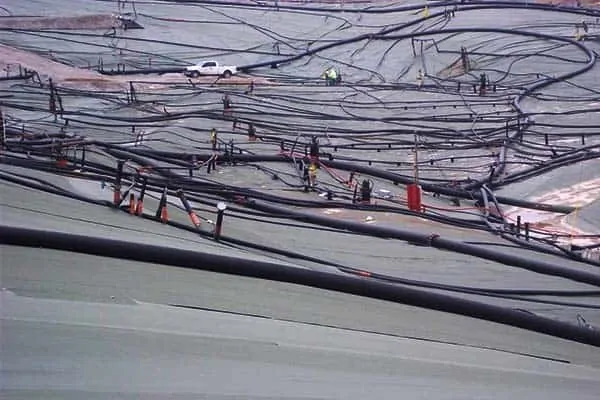
Landfills located in areas with high precipitation usually experience leachate seeps on slopes. The location of leachate seeps varies, and the reason behind the seeps appearing on the slopes varies as well.
As long as the slope does not have its final cover, you can attempt to control leachate seeps no matter where the seep location. There are many remedies known to landfill operators for controlling seeps before the final cover, but leachate seeps below the final cover are not controllable. The reason is the seeps are out of reach, and you have no means to control or mitigate the situation. The only potential solution is a seep management system built under the final cover geomembrane at the time of final cover construction.
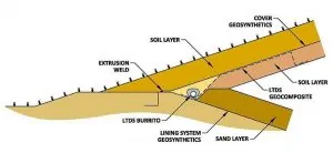
For landfills with slopes extending up to the top of the landfill without terraces, construct a leachate toe drain system (LTDS) at the toe of the slope adjacent to the landfill perimeter berm. The design will collect and convey liquids emanating from seeps further up on the slope (below the final cover geomembrane) to the leachate collection system. See Figure 1.
For landfills with terraces on the slope, construct LTDSs at every terrace. Best practices call for the location at the toe of the slope, above the terrace, the lowest point of that slope. Consequently, the terrace width prevents seep liquids from flowing further down the slope, and the LTDS at the terrace prevents the accumulation of leachate behind the final cover geomembrane at the interior line of the terrace. See Figure 2.
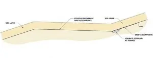
At the lowest point of the terrace, locate a downspout to convey liquids to the leachate collection system at the bottom of the landfill. You will also need a LTDS at the toe of the slope adjacent to the landfill perimeter berm, as discussed above. You may connect the terrace downspouts to the LTDS located adjacent to the perimeter berm to drain the liquids collected at terraces.
To prevent erosion of fines by small streams of liquids flowing down the slope below the final cover geomembrane use this best practice. This design will prevent depressions forming in the top surface of the final cover. First, place a LTDS geocomposite panel from the source of any leachate seep that you identify on the slope right before the construction of the final cover. Connect the panel to the LTDS pipe-gravel burrito at the terrace or perimeter berm. This solution provides a preferential path for liquids coming out of the seep without causing erosion. See Figures 1 and 2.
Place the LTDS geocomposite below the LTDS burrito when simultaneously constructing the burrito and the LTDS geocomposite. When constructing the LTDS burrito ahead of time, place the LTDS geocomposite above the burrito later. In either case, the contact area between the LTDS burrito and the LTDS geocomposite must be free of soil, which could impede the free flow of liquids to the LTDS burrito.
SCS has a 20-year record of accomplishment solving leachate seeps below the final cover geomembrane. Feel free to contact our landfill designers for advice.
About the Author: Ali Khatami, Ph.D., PE, LEP, CGC, is a Project Director and a Vice President of SCS Engineers. He is also our National Expert for Landfill Design and Construction Quality Assurance. He has nearly 40 years of research and professional experience in mechanical, structural, and civil engineering.
Learn more at Landfill Engineering
Pilot-Testing a Novel “Concentrate-&-Destroy” Technology for ‘Green’ and Cost-Effective Destruction of PFAS in Landfill Leachate
One of the recent recipients of EPA’s latest round of small business research grants is investigating a novel technology for treating PFAS in leachate. This project could fill a key technology gap for cost-effectively treating PFAS in landfill leachate. The technology would provide landfill field engineers and decision-makers with a cost-effective solution and mitigate the health impacts as the relevant regulations are rapidly evolving.
Per EPA:
The technology is based on an innovative adsorptive photocatalyst (Fe/TNTs@AC) synthesized by modifying low-cost activated carbon (AC) with a cutting-edge photocatalyst, iron-doped titanate nanotubes (Fe/TNTs). The technology works by first concentrating PFAS in water onto Fe/TNTs@AC, and then completely degrading PFAS under UV or solar light. Bench-scale studies indicated that Fe/TNTs@AC can remove >99% of PFOA or PFOS from water via adsorption within 1 hour and degrade nearly 100% of the adsorbed PFAS within 4 hours of UV irradiation. Complete destruction of PFOA also regenerates the material, allowing for repeated uses.
While conventional AC or resins do not degrade PFAS, and while PFAS-saturated AC or resins are hardly regenerable, PFAS on Fe/TNTs@AC are amenable to efficient photocatalytic degradation, which not only destroys PFAS, but regenerates the material. While direct photochemical treatment of PFAS-laden water is often cost-inhibitive, the new technology employs photocatalytic treatment only for spent Fe/TNTs@AC, which is only a fraction of the raw water volume, and thus consumes much less energy.
Phase I commenced on March 1 and runs through August 31, 2020
For more info, see:
Landfill Leachate – Information and Resources
Landfill operators may add a casing pipe to their leachate force main for additional environmental protection. Consequently, the leachate force main is entirely located inside a casing pipe where the leachate force main is below ground. In the event of a leak from the leachate force main, liquids stay inside the casing pipe preventing leakage into the ground. During monitoring, checking for the presence of leachate inside of the casing pipes is routine.
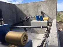
For many years, I designed the installation of an HDPE monitoring manhole at each leachate removal sump station. Designed at the top of the perimeter berm, where the leachate force main is normally located, these manholes normally remain dry. The leachate force main crosses through the manhole without discharging into it. The casing pipes connecting to the manholes are open-ended at the manhole, draining directly into it. Easy to monitor, if liquids are present, you probably have a leak.
Using field operations experience, we improved the design.
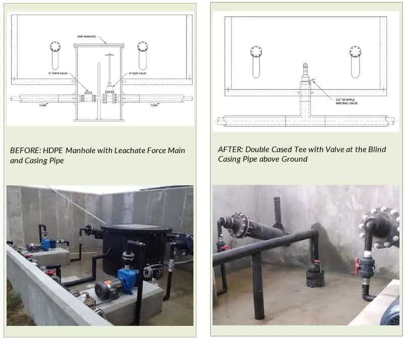
A blind casing pipe above the surface leaves the leachate line exposed for piping purposes. In this design, the casing pipe does not connect to any vessel for monitoring; instead, it has a pressure gauge or small valve on it for pressure monitoring.
If the gauge reads pressure in the casing pipe, it is indicating there is liquid inside the casing pipe; leachate is leaking from the force main and filling the casing pipe causing the pressure to build. If using a valve, monitoring is opening the valve to look for liquid coming out of the casing pipe. Regularly monitored pressure gauges or valves is a standard operating procedure and easily accomplished.
Another in the series, SCS Advice from the Field. It is possible to simplify landfill maintenance and create air space.
Many landfill designers continue to incorporate terraces on the outside slopes of landfills, but not always for sound reasons. Sometimes, terraces are necessary to maintain landfill slopes in stable condition, due to the low shear strength of the foundation soils, or when required according to the specific state or local solid waste rules.
At times designers propose terraces on slopes to collect and convey surface water runoff from a landfill’s higher slopes to a low point on the terrace where the downchute system is located. On paper, it’s easy to show nicely sloping terraces toward a low point, with transverse slopes toward the landfill slope, to control surface water. However, terraces cause significant operational issues for landfill operators. Some of these problems are very apparent, and some realized when a portion of the landfill slope is scheduled to receive a permanent final cover.
Consider these factors during permitting and design, as follows:
It is difficult to shape sloping terraces during waste placement operations; terraces can end up formed horizontally. When it is time to close the landfill’s side slope, significant amounts of soil are placed along the terrace to make it slope toward a low point where the downchute system is located. Normally, permit drawings do not include sufficient details to illustrate these technical issues, and the operator would not have the specific knowledge of such issues at the time of closing the slope.
During waste placement, difficulties arise for the equipment operator (dozer pushing waste and compactor compacting and shaping surfaces) to shape the breaklines and compress waste properly to form the terrace. Lack of compaction near the outside breakline of the terrace makes it susceptible to excessive settlement and can cause the terrace to change shape over time.
Operators shape the transverse slope of the terrace either horizontally, or sloping away from the landfill slope to manage surface water during the landfill’s operational phase. In either case, the slopes could end up formed differently, or in the opposite direction of the slopes in the permit drawings. Closure of the landfill slope requires special attention along with large quantities of soil to shape the terrace similar to what is in the permit drawings. Again, the landfill operator would not know of the additional work and the soil quantities necessary to fix the terrace transverse slope properly.
Settlement in waste causes previously shaped terraces, at a certain elevation ending up lower than the originally shaped terraces. Over time, the terrace originally constructed at a certain elevation and following the permit documents ends up lower in elevation due to waste settlement. Continuously occurring settlement can cause the misalignment of terraces formed at different intervals. At the time of closing, the terrace misalignments become a major problem for the engineer and contractor to meet elevations and shapes previously permitted.
Downchute pipes extend from the highest terrace to the lowest terrace and the surface water management system at the perimeter of the landfill. The downchute pipes are designed to cross the width of each terrace and pickup surface water from each terrace. However, the pipe design is complicated by the terrace transverse slopes toward the landfill slope causes construction complications and increasing the risk of failing to properly collect surface waters at the low point. This particular risk can become drastic when considering waste settlement changing the surface geometry at the inlets to the downchute system, causing costly repairs.
Over the terrace surface, the geocomposite drainage layer in the final cover follows the transverse slope toward the landfill slope and across the width of the terrace. Water in the geocomposite from the higher slope and water from the terrace reach the inside edge of the terrace, with nowhere to go except to follow the longitudinal slope of the terrace along the interior edge. Geocomposite is not designed to carry such a large quantity of water along the interior edge for the entire length of the terrace. Inevitably, problems arise, and potential failures can occur along the terrace. The solution is to install a toe drain along the interior edge of the terrace that collects and conveys water in the geocomposite layer to the low point in the terrace. This toe drain adds another complication to the design of the piping system at the low point of the terrace, where the down chute system is located. Additionally, the cost of the toe drain construction goes up significantly due to logistical complications during construction of the toe drain along the terrace in the middle of the slope-, including the placement of gravel around the toe drain pipe before the geomembrane and geocomposite are covered with the overlying soil.
The access road, to the top of the landfill, normally crosses several terraces located on the landfill slope. The slope surface geometry at the intersection of the access road with the terraces becomes complicated, affecting the alignment of the access road at each intersection point.
Leachate seeps can potentially appear at breaklines on landfill slopes. The inside edges of a terrace are considered breaklines in the landfill slope and are highly susceptible to leachate seeps appearing on the surface. It is common to observe leachate seeps at terraces on landfill slopes. Unfortunately, leachate ponding on the terrace surface from the seeps can easily mix with surface water runoff on the terrace. It’s then carried to the landfill perimeter surface water management ditches and detention/retention areas.
Significant leachate seeps at terraces may require a leachate toe drain system below the final cover geomembrane along the entire length of the terrace; adding cost and another level of complication at the low point of the terrace where the downchute system is located. The leachate in the toe drain system needs to drain to another system at the low point of the terrace, to discharge to the landfill leachate collection system or another liquid management system.
To uncomplicated operations, more landfills are designed without terraces on the slope. Before slope closure management of the surface water runoff is achieved by temporary tack-on berms on the slope and temporary downchute pipes that are constructed and maintained easily. After closure the surface water management is achieved by permanent tack-on berms at certain spacing on the slope; berms are constructed as specified in the permit documents. The swale on the upper side of the tack-on berm conveys surface water runoff from the higher slopes to the low point of the swale on the slope.
The downchute system at the low point of the tack-on berms is simple to construct. These downchutes connect to lateral pipes from lower-level swales collecting surface water from these swales before discharging to the perimeter surface water management system. The aforementioned design does not require significant maintenance.
Maximizing Airspace
Terraces decrease potential airspace within the permitted footprint of the landfill. Wasted airspace on landfill slopes is substantial and can be in the order of tens of millions of dollars depending on the size of the landfill. Owners/Operators request airspace loss calculations to emphasize the financial impact of terraces on their bottom line.
One recent evaluation for a 170-acre, 250-ft tall landfill with seven terraces lost approximately 7,500,000 cubic yards of air space. The tipping fee of $80 per ton results in an estimated value of $64.00 per cubic yard of compacted waste. Therefore, the estimated value of the airspace loses due to the terraces at this landfill site is estimated to cost $480,000,000, nearly half-a-billion dollars of the bottom line.
 This author, Ali Khatami, Ph.D., P.E. with SCS Engineers, has over 30 years of landfill design and construction for municipalities and private firms. He has first-hand knowledge of the satisfaction and cost-effectiveness of no-terrace systems by landfill operators he has worked with over three decades; many of whom changed their permits to eliminate terraces to take advantage of the airspace and operational benefits.
Ask our authors questions, by writing to or contacting Dr. Khatami directly.
I read your informative blog regarding recommendations for jet cleaning leachate collection pipes. I have a question.
QUESTION: Say a landfill only has access to one end of a leachate pipe. This would be a situation where a new cell was built, where the uphill side of the cell butts up against an existing, pre-subtitle D cell with no leachate collection pipe. In other words, the uphill side of the new leachate pipe simply terminates rather than tie into an existing pipe.
To add to the issue, no vertical cleanout/riser pipe was installed on the uphill end (as this may impede waste operations in the area). There are of course riser and cleanout pipes and a sump on the downhill side for normal leachate collection. I would imagine that pumping water from the accessible side would push out any solids through the perforations into the leachate aggregate bedding, and may cause clogging there.
Is it possible, or reasonable, to flush this new leachate line?
ANSWER: There is always a possibility that a portion of dislodged material from the interior walls of the pipe will pass through pipe perforations and enter the gravel bedding around the pipe. However, due to the pipe slope, the great majority of the separated material flows down the pipe to the lowest point where it can be removed using a vac-truck.
Keep in mind also that, it’s true that leachate can partially flow through the bedding gravel toward the sump, but the role of the gravel is primarily protecting the pipe against compressive loads of waste above. Partial clogging of gravel around the pipe should not be considered as a malfunction of the system. Partial clogging of gravel normally may occur near the bottom portion of the gravel pack, which still allows leachate flow through gravel to pipe perforations above any clogged zone below.
In several instances, when a portion of a leachate collection pipe was opened up after being in service for a while, it did not support the idea of a clogged zone in the gravel pack. What was observed, included discolored gravel due to fine particles settling (from filtered leachate through geotextile) on gravel particles and a bit of the same particles near the bottom of the gravel pack.
I’ve never observed severe clogging of the gravel pack.
Thanks for your interest in the subject, and please stay in touch with any other questions. SCS freely shares best practices and advice within our industry; email us at
About the Author: Ali Khatami, PhD, PE, LEP, CGC, is a Project Director and a Vice President of SCS Engineers. He is also our National Expert for Landfill Design and Construction Quality Assurance. He has over 40 years of research and professional experience in mechanical, structural, and civil engineering.
Understanding the entire range of wastewater management and disposal alternatives can be a daunting task, particularly as increasingly stringent surface water discharge standards take effect or as zero discharge facilities find the management of their waste liquid needs changing over time. Former solutions are no longer options or may be too costly. One alternative that is rapidly gaining traction is deep injection wells.
Deep well injection is a viable leachate management option in many parts of the United States, yet it is often screened out as a possible alternative due to a lack of understanding of the technology or gross misconceptions about its acceptance or applicability. The purpose of the Monte Markley’s paper The Basics of Deep Well Injection as a Leachate Disposal Option is to present the basic technical, economic and regulatory considerations of deep well injection as a technology a facility should evaluate when considering the applicability of geologic sequestration of leachate.
Technical criteria discussed are potential disposal volumes, geologic suitability, chemical compatibility, pre-treatment requirements, and leachate chemistry. The economic considerations are evaluated based on the technical criteria noted above, management of public perception/relations, current leachate management expenditures, the service life of the asset and risk to develop accurate capital, O&M costs, and return on investment. Regulatory considerations include the role of state vs. federal primacy for each state, the general stance of regulatory acceptance in specific areas of the United States, and a discussion of the permitting process and typical reporting requirements.
These key considerations are then integrated into an overall suitability evaluation that an owner can utilize to accurately determine if deep well injection is a viable option and, if so, how to educate other stakeholders and manage the process of implementation as a project moves forward.
About the Author: Monte Markley, PG, SCS Engineers
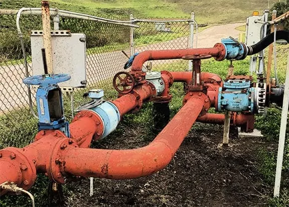
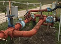
Regulatory and siting restrictions are such that many solid waste operators prefer to expand their existing landfill footprint as much as possible instead of finding a new disposal footprint at a different location. As landfills are getting larger in height and greater in footprint area, the location of leachate tanks, leachate ponds, or discharge points to an on-site or off-site leachate treatment plant usually does not change. A larger footprint means leachate force mains are getting longer forcing the existing pumps to work harder to push leachate through the system to a target point. Some operators carry on with the same pumps for decades and do not monitor the performance of the pumps after expanding the landfill footprint, which could be more costly in the long-term.
Hydraulic Evaluations for Lateral Expansion
The longer leachate force main with possibly additional bends in the line increases friction in the line and causes flow rates to reduce to unexpected levels. We recommended that landfill operators evaluate the performance of the existing pumps along with new pumps when designing a lateral expansion. Such an evaluation may require hydraulic analysis of the entire network of pipes along with pumps, or only the segment of the network affected by the expansion. However, the effort is minimal in comparison to the operating costs of inefficient flow and overtaxing the equipment.
Sometimes the results of a hydraulic evaluation may require up-sizing all or specific pumps in leachate sumps because not enough flow can go through the force main due to high friction loss in the expanded leachate force main. Up-sizing pumps may be achievable depending on the type of the leachate sump, i.e., riser system or vertical manholes. If the up-sized pump in a riser system is too long to fit inside a riser system, or so long that it makes routine maintenance too cumbersome, your engineer may consider enhancing the functionality of the design.
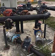
Inline and Offline Pumps
Booster pumps located along an expanded leachate force main can certainly be an option. Booster pumps can be the inline or offline type. Install the inline pumps on the actual force main, and position the offline type on the side so that liquids go through bends and elbows to reach the pump, and again through bends and elbows to get back in the force main. In either case, the booster pump adds hydraulic energy to the flow inside the force main to push the liquids at a compensated pressure through the remainder of the force main and to the target point.
Operators need to be aware of the dynamic nature of the leachate piping network and the role of booster pumps in the dynamic environment. Changes to the flow in the force main may change following a landfill expansion when the new cells are coming online increasing leachate generation. Alternatively, after closing portions of the landfill slopes, that decreases leachate generation over time. Sometimes booster pumps have to be up-sized or downsized depending on the flow and pressure in the system.
Optimizing Performance, Reduce O&M Costs
The cost of replacing pumps, up-sizing, or downsizing, is insignificant compared to the revenue that landfills generate. Proper adjustment of the pumping system keeps the entire network operating at the appropriate range of pressure, and velocity in the line; increasing the life of the pumping system. Less wear and tear on the system produces a reduction in maintenance costs along with less equipment downtime.
Lower maintenance requirements may also reduce the number of personnel required to keep the system in operational condition. Landfills with a large pumping system employing a second technician because of the high maintenance of multiple pumps may find a single technician sufficient for the upkeep of the system. Proper sizing of pumps and operating the pumping system as designed within the evaluation parameters can significantly reduce the cost and frequency of pump maintenance.
 About the Author: Ali Khatami, PhD, PE, LEP, CGC, is a Project Director and a Vice President of SCS Engineers. He is also our National Expert for Landfill Design and Construction Quality Assurance. He has nearly 40 years of research and professional experience in mechanical, structural, and civil engineering.
Landfill Engineering and Leachate Management
Corporate Headquarters