Understanding the entire range of wastewater management and disposal alternatives can be a daunting task, particularly as increasingly stringent surface water discharge standards take effect or as zero discharge facilities find the management of their waste liquid needs changing over time. Former solutions are no longer options or may be too costly. One alternative that is rapidly gaining traction is deep injection wells.
Deep well injection is a viable leachate management option in many parts of the United States, yet it is often screened out as a possible alternative due to a lack of understanding of the technology or gross misconceptions about its acceptance or applicability. The purpose of the Monte Markley’s paper The Basics of Deep Well Injection as a Leachate Disposal Option is to present the basic technical, economic and regulatory considerations of deep well injection as a technology a facility should evaluate when considering the applicability of geologic sequestration of leachate.
Technical criteria discussed are potential disposal volumes, geologic suitability, chemical compatibility, pre-treatment requirements, and leachate chemistry. The economic considerations are evaluated based on the technical criteria noted above, management of public perception/relations, current leachate management expenditures, the service life of the asset and risk to develop accurate capital, O&M costs, and return on investment. Regulatory considerations include the role of state vs. federal primacy for each state, the general stance of regulatory acceptance in specific areas of the United States, and a discussion of the permitting process and typical reporting requirements.
These key considerations are then integrated into an overall suitability evaluation that an owner can utilize to accurately determine if deep well injection is a viable option and, if so, how to educate other stakeholders and manage the process of implementation as a project moves forward.
About the Author: Monte Markley, PG, SCS Engineers
Comments were submitted to the EPA from NWRA/ SWANA regarding the EPA’s Advance Notice of Public Rule Making (ANPRM) for revisions to Subtitle D, and in particular potential revisions regarding the bulk liquids addition. Subtitle D prohibits bulk liquids additions with the exception of leachate recirculation, and the RD&D permit process allows bulk liquids. Bob Gardner of SCS Engineers was involved in the development of the joint NWRA/SWANA comment letter.
EPA has indicated that they are considering adding a “wet landfill” definition to Subtitle D; however, the Industry strongly advised against doing so. The letter addresses this issue and the reasons for recommending against a separate “wet landfill” definition.
Industry Association’s Comments
Deep injection wells (DIW) mean different things in different parts of the country. In the midwest DIWs have been used for decades to dispose of industrial wastewaters, mining effluent, and produced water from oil and gas production activities and are from 3,500 feet to more than 10,000 feet deep. In Florida, deep injection wells have been used since the 1960s; however, they are used to dispose of treated municipal wastewater, unrecyclable farm effluent, and in some cases landfill leachate. DIWs in Florida range from 1,000 feet to around 4,500 feet deep.
This is a two-part blog, the first part discussing what constitutes a DIW, their general features, their cost relative to other wastewater management alternatives, and the range of industrial wastewaters suitable and safe for disposal. The second part, covered in the next SCS Environment issue, will be on the challenges for deep well developers created by public and environmental organizations, and strategies to counter misinformation and means to obtain consensus from stakeholders.
A DIW construction is a series of casings set in the ground where the initial casing starts out large and subsequent casings become smaller in diameter, progressively telescoping downward. Casing materials are typically steel alloys or fiberglass for better chemical resistance. As a casing is set and rock is drilled out, the next casing is set and cemented with a chemically resistant grout. The process continues with each progressively deeper casing. These redundant “seals” are what keep the injected liquid from escaping into the protected aquifers.
A DIW typically has three upper casings to protect the aquifers and isolate the wastewater to the desired disposal zone. The inner casing, called the injection tube, extends to the injection zone. Mechanical packers seal the space between the injection tube and the last casing with the annular. The resulting annular space is filled with a non-corrosive fluid. This fluid is put under pressure to demonstrate the continuous mechanical integrity of the well. The annulus is monitored for potential leaks, which would register as a loss in pressure and promptly stop the injection. Figure 1 is a simplified view of a DIW casing system used in south Florida.
Vertical turbine pumps working in conjunction with a holding tank, which is a used to smooth out the fluctuating flow of the wastewater feed pumps, propel the liquid down the well. As part of the permitting efforts, a chemical compatibility study is conducted to determine the level of pre-treatment if any to protect the well components and minimize downhole plugging. Municipal wastewater effluent is regulated differently and must receive at least secondary treatment before injection.

In the Midwest, DIWs are constructed to the same EPA criteria with a wide range of operating conditions. Some wells take fluid under gravity with no pumping, while others require higher pressure pumps that exceed 2,500 psi for injection. This blog focuses on wells used in Florida and typical fluid types and operational parameters.
In central and south Florida the injection zone lies below the underground sources of drinking water (USDW) which is the depth at which water with a total dissolved solids (TDS) concentration exceeds 10,000 parts per million (ppm); or the “10,000 ppm line”. This water is considered to be unusable in the future as a drinking water source. In parts of Florida, the injection zone is dolomite overlain by a series of confining units up to 1,000 feet thick made up principally of limestone with permeability several orders of magnitude less than the injection zone. (1)
In central and south Florida the target injection interval is the “Boulder Zone,” reportedly named because drilling into the formation often broke off pieces of the formation and made drilling difficult. The Boulder Zone is also known as the lower portion of the Floridan Aquifer. Later down-hole imaging technologies revealed this zone to be characterized by highly fractured bedrock and large karstic caverns, and the ability to inject relatively high flow rates with relatively little backpressure. It is not uncommon for Florida DIWs to have well flow rates exceeding 15 million gallons per day (MGD) and backpressures ranging from 30 up to 100 pounds per square inch (psi).

The versatility of the DIW in Florida to accommodate numerous different types of wastewater is an advantage. DIWs are being used on a large variety of waste streams that continues to expand, including:
Any wastewater considered for disposal must be compatible with the target formation and the final casing material. Therefore, depending on the wastewater, it may be straightforward to use existing industry references to confirm compatibility. In some cases, laboratory bench tests may be necessary to confirm compatibility.
Compatibility also includes the potential for creating unwanted microbial growth and scale formation within the injection interval. Growth and scale can happen with effluent containing sulfur or ammonia, two food sources for microorganisms or wastewaters supersaturated with minerals. Unless planned for and evaluated properly, both of these items have the potential to grow and clog the formation around the well, significantly reducing flow and increasing back pressure. This can result in higher energy costs, regulatory action and significant, unplanned costs to rehabilitate the well.
Another significant aspect of municipal wastewater is that they are primarily composed of freshwater and thus when injected into the highly saline Boulder Zone or similar saline zones, will tend to have a vertical migration component because of the density difference and greater buoyancy than the target zone. A few wells have been taken out of service because the seals designed to prevent this migration failed and allowed wastewater to seep upwards into the USDW.
The US EPA Underground Injection Control (UIC) program is designed with one goal: protect the nation’s aquifers and the USDW. There are several protective measures in a DIW that are intended to meet this objective;
The U.S. EPA conducted a study in 1989-1991 of health risks comparing other common and proven disposal technologies to deep wells injecting hazardous waste. The U.S. EPA concluded that the current practice of deep well injection is both safe and effective, and poses an acceptably low risk to the environment. In 2000 and 2001 other studies by the University of Miami and U.S. EPA, respectively, suggested that injection wells had the least potential for impact on human health when compared to ocean outfalls and surface discharges(3). William R. Rish examined seven potential well failure scenarios to calculate the probabilistic risk of such events.These scenarios included four types of mechanical failures, two breaches of the confining units, and the accidental withdrawal of wastes. The overall risk was quantified by Rish as from 1 in 1 million (10-6) to 1 in 100 million (10-8) (4), which is no greater than the current EPA risk criteria for determining carcinogen risk. As a comparison, 10-6 is the same risk level used by EPA for contaminants in soil or groundwater that are a known carcinogen.
There are several studies in Florida conducted by researchers and practitioners in the deep injection well field to assess the actual potential for municipal wells to contaminate the USDW. The maximum identified risk associated with injection well disposal of wastewater in south Florida is the potential migration of wastewater to aquifer storage and recovery (ASR) wells in the vicinity of injection wells (Bloetscher and Englehardt 2003; Bloetscher et al. 2005).
In a 2007 study, 17 deep wells in south Florida, used for municipal waste disposal, that had known upward migration into the USDW, were evaluated to develop a computer model to simulate these phenomena and extrapolate vertical migration over longer time periods. The results indicated that the measured vertical hydraulic conductivities of the rock matrix would allow for only minimal vertical migration. Even where vertical migration was rapid, the documented transit times are likely long enough for the inactivation of pathogenic microorganisms (5).
In a 2005 study of 90 South Florida deep injection wells, the authors took actual field data and constructed a computer model calibrated to actual operating conditions. The intent was to model performance of two injection wells in the City of Hollywood, Florida that the authors were familiar with and to determine the likelihood of migration, and what might stop that migration. Density differential and diffusion were likely causes of any migration. No migration was noted in Hollywood’s wells. The preliminary results indicate that Class I wells can be modeled and that migration of injectate upward would be noticed relatively quickly (3).
A deep injection well lifecycle cost compares favorably with other traditional waste treatment and disposal techniques. A life-cycle cost includes the capital cost and operating and maintenance costs for the useful life of the system. On a recent project, the wastewater for disposal was groundwater contaminated with ammonia nitrogen from a former landfill. The estimated groundwater recovery rate and the deep injection well disposal rate was calculated to be 1.2 million gallons per day (MGD). The proposed deep well was designed to have a final casing of 12-inch diameter, an 8-inch diameter injection tubing to a depth of 2,950 feet, and below that approximately 550 feet of open bore hole. The lifecycle cost estimate comparison to other viable technologies is shown in the Table below.

In this case, there were no projected revenues, so the alternative with the lowest net present value (NPV) would technically be the preferred alternative. Even though the aerated lagoon had the lowest NPV, it was ultimately judged too risky with a long break-in treatment period and significantly more space for treatment ponds needed.
The increasingly stringent surface water discharge standards are an ongoing challenge for industries generating a wastewater stream. DIW’s should be considered as a potentially viable option for long-term, cost-effective wastewater disposal, where a viable receiving geologic strata exists and when wastewater management alternatives are evaluated. In Florida, they currently provide an environmentally sound disposal option for many regions.
Within the SCS Engineers’ website, you will find the environmental services we offer and the business sectors where we offer our services. Each web page offers information to help you qualify SCS Engineers and SCS’s professionals by scientific and engineering discipline.
We provide direct access to our professional staff with whom you may confidentially discuss a particular environmental challenge or goal. Our professional staff work in partnership with our clients as teams. We are located according to our knowledge of regional and local geography, regulatory policies and industrial or scientific specialty.
It’s been 10 years since the first Research, Development, and Demonstration (RD&D) Plans were approved allowing liquids to be applied to municipal solid waste landfills in Wisconsin. What have we learned?
Under an approved RD&D Plan, landfill operators can apply liquids other than recirculated leachate to the waste at municipal solid waste landfills. The RD&D Rule was published by US EPA in 2004, and states had the option of adopting the rule and issuing RD&D approvals. Wisconsin was an early adopter, and 13 of the approximately 30 landfill sites in the US with RD&D approvals are in Wisconsin.
This presentation will look at data from the Wisconsin landfills with RD&D Plans. Each site is required to report annually on a very detailed basis. For this presentation we will zoom out and look at the data on an aggregated basis to address big-picture questions. What are the trends in volumes applied for leachate recirculation versus RD&D Liquids? How do these volumes compare with precipitation? What liquid waste streams have been accepted and how have they been applied? How has RD&D liquid application affected landfill gas generation?
We will also provide an update on the regulatory status of the RD&D rule. On May 10, 2016, a final federal rule was published that revised the maximum permit term from 12 years to 21 years; however, WDNR will have to adopt this change in order for it to be available to Wisconsin landfills.
Removing biological growth in landfill leachate collection pipes is an important maintenance measure to keep the pipes in operable condition. High-pressure jet cleaning of the pipes on a regular schedule is performed in accordance with best practices and regulatory policy. For example, in Florida, solid waste rules require leachate collection pipes to be either jet cleaned every five years or videoed to confirm that the pipes are in operational condition. Of course, if the video shows that cleaning is necessary, the operator performs the maintenance and submits a report to the appropriate agency.
The spent jetting liquids contain a mix of calcite and microorganisms that have been removed from pipe walls and perforations. The liquid mixture flows to the lowest point in the pipe and enters the sump medium, which is typically composed of one to three-inch size rock. A drawback of jet cleaning is that when the pipes are cleaned, the spent jetting liquids enter the sump medium, thereby using essential leachate storage space in the sump. The calcite and microorganisms that were removed from the leachate piping are now present in the sump and will reduce the sump capacity and cause bottlenecks within the perforations in the riser pipe(s). Over time, this buildup will prevent the flow of leachate in the sump into the riser pipe. Without flow into the riser pipe, leachate removal from the sump becomes impossible, causing expensive operations and compliance issues for the landfill operator.
Clogging of the sump medium is a slow process; many sumps do not show indication of the impact of buildup for years. Landfill operators typically don’t use jet cleaning equipment equipped with vacuum features to remove the spent liquids from the pipe during cleaning. SCS recommends that this potential issue is discussed with the cleaning contractor in advance to account for the problems that can occur. For shallow landfills, contractors could provide a vacuum line inserted into the cleanout riser to remove the spent liquids as the pipe is cleaned. For deep landfills, the cleaning contractor can provide a temporary pump inserted inside the riser to remove the spent liquids.
To prevent excessive biological growth, jet cleaning of the riser pipes every time the leachate collection pipes are cleaned will significantly reduce clogging of the riser pipe perforations. Unmaintained riser pipes block leachate from entering the riser, preventing liquid removal and causing compliance issues when found.
Ask the author a question: Dr. Ali Khatama
 Thanks to you, our clients, SCS Engineers has received many awards and industry recognitions for research achievements and technology innovations. Engineering News-Record (ENR) recently released the Top 500 Design List, ranking SCS Engineers in the top 100 for the 9th year in a row. In the same publication, SCS is ranked in the Top 10 Sewerage/ Wastewater Firms.
Thank you for your friendship, your business, and the opportunity to serve you.
SCS Engineers met a tight, non-negotiable regulatory deadline to get the new plant on-line while meeting non-toxic effluent standards.
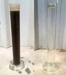
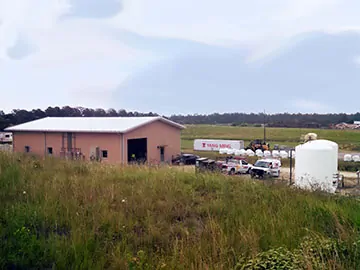
Everyone enjoys before and after pictures; just look at the results New Hanover County’s program is producing. This and other County programs are helping this North Carolina county reduce reliance on landfill disposal while creating a comprehensive and sustainable solid waste management system that is protective of the environment.
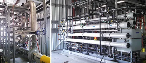
In 2016 a new wastewater treatment plant was commissioned at the New Hanover County Landfill. The new facility processes approximately 65,000 gallons per day (GPD) of leachate using state-of-the-art ultrafiltration (UF) and reverse osmosis (RO) technologies to meet or exceed federal and state treatment standards.
The raw leachate is pre-treated in an existing aerobic lagoon followed by a sequencing batch reactor (SBR) to reduce organic constituents. The pretreated effluent then flows into the membrane system. Using state-of-the-art membrane filtration technology, including ultrafiltration (UF) pictured at lower left, and a reverse osmosis (RO) system, pictured lower right, to produce crystal clear, effluent discharged to an upper tributary of the Cape Fear River.
The new facility can process 75,000 GPD and the Wastewater treated through the new system meets state Drinking Water standards for quality.
Tough surface water discharge standards and predictable performance in cold weather drove the design to use UF/RO systems. The results are impressive; metals including arsenic are BDL, ammonia <0.2 ppm, and TSS < 2 ppm. The system produces approximately 13,000 GPD of RO concentrate that is pumped to the working face and safely disposed of in the landfill. The County has certified operators that have played a big role in getting the plant shaken down and running smoothly.
“New Hanover County is an industry leader in adopting proven technologies to better manage solid waste, and protect the environment. This kind of planning and approach can benefit many other public works departments,” stated Bruce Clark, PE, BCES, LEED AP®, and SCS Engineers National Expert on Waste Conversion.
As Joe Suleyman, the County’s Environmental Management Director put it, “Let’s face it – people move to New Hanover County because they love to be in, on, or near the water. Our technical staff is composed of very talented folks who have environmental science and biology backgrounds. They believe in what they’re doing to help protect our delicate coastal environment, and this state-of-the-art system is a huge stride towards meeting our own expectations and those of the citizens we serve.”
See more case studies, services, and professionals on the SCS Engineers – Liquids Management Website
Over years of working on operations and maintenance of landfill gas collection and control systems and leachate management systems, SCS found that too many times data is collected and no one has the time to review and analyze it for improved decision-making.
As an industry-wide issue, SCS developed systems to streamline the process using technology and our field expertise to help perform routine and sometimes complex data analysis and to automatically push reports and alerts to operators, engineers, and project managers.
The improvements are dramatic; by removing human error from reviewing pages of data we now focus our time and energy on what really matters, using what the data tells us to make informed decisions. Let’s put the technology into the context of everyday operations – identify, troubleshoot, and solve landfill gas and leachate challenges.
This SCS paper illustrates several sites using integrated systems for data collection and analysis and how they are used to identify, troubleshoot, and solve real problems in an effective and efficient manner.
Privately share this article using the email icon on the left navigation bar. Print the article using the Download icon just under the article, or your browser commands.
About the Authors:
David P. Hostetter, PE, Denver, Pennsylvania
Phil Carrillo, Huntington Beach, California
Darrin D. Dillah, Ph.D., PE, BCEE, Reston, Virginia
Corporate Headquarters