Solid waste engineers prepare large sets of drawings for landfill design. The set typically includes several sheets of plan drawings, large-scale cross-sections of the landfill, and many cross-section and plan details for various components of the landfill. Always use the waste limit as the baseline for the entire design. The waste limit need not coincide with the actual outer boundary of the waste material, depending on the landfill’s cross-section at the perimeter berm. The most convenient line that clearly defines the waste limit and is easily recognizable is the inside edge of the perimeter berm top surface. The actual location of the most outerly point of the waste may be a couple of feet away from the inside edge of the perimeter berm, but that does not normally matter. Using any other line as the waste limit can complicate the design.
Engineers should design the perimeter berm with the least curvature, if possible. Straight lines simplify landfill design and prevent the need for complex surface-water drainage swales at the landfill’s final cover and downchute locations. Avoid concave corners as much as possible. Concave corners are problematic for the final cover system drainage system. Due to the geometry of concave surfaces, water in the final cover geocomposite converges toward the toe of the slope. It could potentially increase the head of water in the final cover geocomposite. Final cover geocomposites are normally designed for straight-line 3:1 or 4:1 slopes. The convergence of water over concave surfaces is not typically analyzed during the design of final cover systems. Such conditions can result in water head exceeding the geocomposite thickness and partially or fully saturating the overlying soil. Such conditions should be avoided whenever possible.
The waste limit at the inside edge of the landfill perimeter berm governs the design of the lining and final cover systems, which come together at the perimeter berm. Designing the landfill perimeter so that the bottom lining system and the final cover barrier layer meet at the inside edge of the perimeter berm (the limit of waste) is the most widely recognized way to set design lines in landfill drawings. That allows the final cover geomembrane to be welded to the bottom lining system geomembrane, sealing the landfill interior space. Sealing the landfill has numerous benefits, including preventing landfill gases from escaping the landfill’s interior, preventing leachate seeps from escaping the lined system, and increasing gas collection.
A significant benefit of the limit of waste being the meeting point of the top and the bottom barrier layers is that the final cover geomembrane can be welded to the bottom geomembrane, eliminating the need for a final cover anchor trench. Designs with a separate anchor trench for the final cover geomembrane should be avoided. Also, designs with the final cover geomembrane placed inside the bottom lining system anchor trench should also be avoided.
By defining the limit of waste as the inside edge of the perimeter berm, the site owner/ operator will clearly know the outer limit of waste during landfilling operations, which can be avoided. Waste placement and follow-up slope maintenance become much easier when the waste limit is set at the inside edge of the perimeter berm. Generally, the actual outer point of the waste mass is a few feet away from the inside edge of the berm. Operators use the inside edge of the perimeter berm to set an offset line for the actual waste limit during waste placement, allowing waste to be located a few feet from the top of the lined slope.
About the Author: Dr. Ali Khatami
Additional Resources:
Landfills located in areas with high precipitation usually experience leachate seeps on slopes. The location of leachate seeps varies, and the reason behind the seeps appearing on the slopes varies as well.
As long as the slope does not have its final cover, you can attempt to control leachate seeps no matter where the seep location. There are many remedies known to landfill operators for controlling seeps before the final cover, but leachate seeps below the final cover are not controllable. The reason is the seeps are out of reach, and you have no means to control or mitigate the situation. The only potential solution is a seep management system built under the final cover geomembrane at the time of final cover construction.
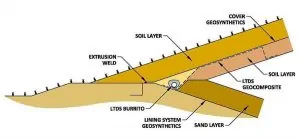
For landfills with slopes extending up to the top of the landfill without terraces, construct a leachate toe drain system (LTDS) at the toe of the slope adjacent to the landfill perimeter berm. The design will collect and convey liquids emanating from seeps further up on the slope (below the final cover geomembrane) to the leachate collection system. See Figure 1.
For landfills with terraces on the slope, construct LTDSs at every terrace. Best practices call for the location at the toe of the slope, above the terrace, the lowest point of that slope. Consequently, the terrace width prevents seep liquids from flowing further down the slope, and the LTDS at the terrace prevents the accumulation of leachate behind the final cover geomembrane at the interior line of the terrace. See Figure 2.
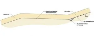
At the lowest point of the terrace, locate a downspout to convey liquids to the leachate collection system at the bottom of the landfill. You will also need a LTDS at the toe of the slope adjacent to the landfill perimeter berm, as discussed above. You may connect the terrace downspouts to the LTDS located adjacent to the perimeter berm to drain the liquids collected at terraces.
To prevent erosion of fines by small streams of liquids flowing down the slope below the final cover geomembrane use this best practice. This design will prevent depressions forming in the top surface of the final cover. First, place a LTDS geocomposite panel from the source of any leachate seep that you identify on the slope right before the construction of the final cover. Connect the panel to the LTDS pipe-gravel burrito at the terrace or perimeter berm. This solution provides a preferential path for liquids coming out of the seep without causing erosion. See Figures 1 and 2.
Place the LTDS geocomposite below the LTDS burrito when simultaneously constructing the burrito and the LTDS geocomposite. When constructing the LTDS burrito ahead of time, place the LTDS geocomposite above the burrito later. In either case, the contact area between the LTDS burrito and the LTDS geocomposite must be free of soil, which could impede the free flow of liquids to the LTDS burrito.
SCS has a 20-year record of accomplishment solving leachate seeps below the final cover geomembrane. Feel free to contact our landfill designers for advice.
About the Author: Ali Khatami, Ph.D., PE, LEP, CGC, is a Project Director and a Vice President of SCS Engineers. He is also our National Expert for Landfill Design and Construction Quality Assurance. He has nearly 40 years of research and professional experience in mechanical, structural, and civil engineering.
Learn more at Landfill Engineering
Corporate Headquarters