
The Environmental Protection Agency (EPA) has recently proposed increases in renewable fuel volume requirements across all types of biofuels under the Renewable Fuel Standard (RFS) program. The proposed increases would boost renewable fuel production and provide for ambitious yet achievable growth.
The Clean Air Act requires EPA to set annual RFS volume requirements for four categories of biofuels: cellulosic biofuel, biomass-based diesel, advanced biofuel, and total renewable fuel. EPA implements the program in consultation with the U.S. Department of Agriculture and the U.S. Department of Energy.
EPA will hold a public hearing on this proposal on June 9, 2016, in Kansas City, Missouri. The period for public input and comment will be open through July 11, 2016.
For more information on the proposal, see www.epa.gov/renewable-fuel-standard-program/proposed-renewable-fuel-standards-2017-and-biomass-based-diesel.
For more information on the public hearing, see www.gpo.gov/fdsys/pkg/FR-2016-05-25/pdf/2016-12358.pdf.
This innovative sustainable materials management approach involves strategically picking up loads from businesses that generate similar types of discards. The linked article discusses the approach of following simple procedures governing selective routing in the commercial space.
Using a phased methodology, it is possible to turn a high-disposal garbage collection system into a high-diversion recycling system, without incurring additional costs or losing collection revenue. Dumpsters behind shopping plazas and other sites can become opportunities at the center of a thriving materials recovery program.
About the Authors:
Richard Gertman is the owner of For Sustainability Too in San Jose, CA.
Tracie Onstad Bills has been in the Environmental and Resource Material Management Field for over 20 years. Her expertise revolves around commercial recycling technical assistance, environmental purchasing, large venue and event zero waste programs, research and sustainability planning, garbage hauler franchise compliance and review, construction and demolition program / ordinance analysis and writing, climate inventory compilation, research and feasibility studies to help clients with comprehensive waste prevention and zero waste programs. Ms. Bills has a BA in Environmental Science from San Jose State University, is a CRRA Board member and belongs to the SWANA Gold Rush Chapter, National Recycling Coalition and the Northern California Recycling Association. Contact Tracie here.
Glass accounts for almost 5% of the municipal solid waste stream; state and local agencies have set ambitious zero waste goals; many agencies are not ready to give up on glass recycling. How do they manage to keep their programs viable despite the cost of processing, transportation, and the challenge of cross contamination?
Sustainable Solid Waste Managment Planning and Programs
East Alton Defense Area Rehabilitation Project Receives Illinois Governor’s Affordable Housing Champion Award. SCS Engineers provides environmental services that help move redevelopment project forward. – Congratulations RISE!
Mark Stroker, Director of Real Estate Development, RISE St. Louis, informed the SCS Engineers team about the honor, saying he felt “a great deal of pride and appreciation that Emerald Ridge was selected by IHDA [Illinois Housing Development Authority] as the Champion’s Award winner for excellence in affordable housing development for 2016.”
Mr. Stroker went on to tell the SCS team that, “It is an extraordinary honor and represents a long and collaborative effort… This was a tough project and wouldn’t have been possible without all of your help.” He attended the Illinois Governor’s Conference in late March 2016, where he accepted the award and discussed the project with conference attendees.
In his notification to Mr. Stroker about the award, Benjamin Fenton, IHDA’s Housing Coordination Services Manager, explained that three nominees are chosen for this award every year for distinguished developments, initiatives, or programs in affordable housing. The nominees stand out for their commitment to serving the Annual Comprehensive Housing Plan focus areas and one or more of the State’s Priority Populations, and for having positive impacts on the community in which they are located.

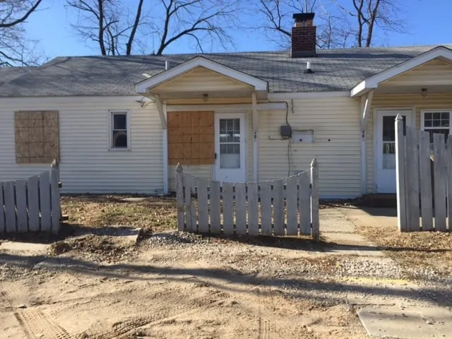
Before it was redeveloped, The Emerald Ridge Development was known as the “Defense Area,” and it consisted of 18 one- and two-story multi-family buildings containing approximately 80 apartments. The Defense Area was built by the Federal government as temporary housing in the early 1940’s to accommodate workers at the nearby Olin ammunition plant during the war effort. After the war, these barracks-style buildings were not dismantled as originally planned but were sold off to private owners. Over the years, they were re-sold multiple times, and the condition of most of the buildings became more and more deteriorated, in addition to being constructed with asbestos-containing materials and lead-based paints.
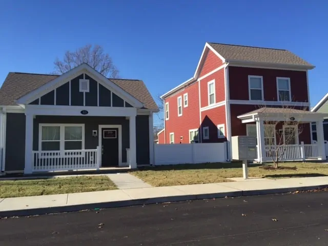
Residents were temporarily relocated, and the old buildings were demolished and replaced with 46 newly constructed, high-efficiency single-family homes. The residents who lived in the area when the redevelopment project commenced were given the opportunity to rent homes in the new development, and some accepted. The rechristened Emerald Ridge Development is located in the Village of East Alton, Illinois, and the new single-family homes are affordable to families earning 60% of the Area Median Income, which includes nearly two-thirds of the residents of East Alton.

Services that SCS Engineers provided at the site included lead and asbestos abatement sampling and specifications, asbestos abatement management, subsurface investigation for a Phase II ESA, NESHAP demolition inspections, and two Phase I ESAs to assess the property for potential environmental impairments, to satisfy IHDA requirements, and to satisfy the CERCLA requirements to qualify for landowner liability protection.
Stephanie Hill, SCS Project Director, said: “I am honored to be part of the RISE team that brought so much value to the community.” Ms. Hill offered special thanks to Randy Homburg, SCS Geologist and Project Manager, for his work on this redevelopment project, and to the other SCS team members who performed the environmental site assessments.
The drainage layers of landfill final covers normally go through a rigorous flow capacity evaluation. This evaluation is necessary to ensure that the volume of water reaching the drainage layer due to percolation of precipitation water through the final cover upper soil layer will not overwhelm the drainage layer in its flow path. If the flow volume in the geocomposite drainage layer is greater than the capacity of the drainage layer, water will exit the geocomposite and enter the overlying soil. The water entering the soil layer can easily saturate the lower portion of the soil layer, which will affect the stability of the slope. The geocomposite should always be designed to have a flow capacity greater than the flow rate of water running through it.
Concave areas of a landfill slope experience flow patterns quite different from slopes that go straight down. Slopes with concaved geometry have an unequal crest and toe lines – the toe line being smaller than the crest line. As a result, the width of the concaved slope decreases as the distance from the crest line increases in the downward direction. The narrowest width of the concaved slope is at the toe of the slope. The drainage layer on the slope experiences the same width change from the crest line to the toe line. This means that the overall width of the channels that carry water within the geocomposite drainage layer decreases toward the toe line, and, therefore, the depth of water in the channels increases. This phenomenon is referred to as flow convergence, and the convergence is toward the vertical centerline of the concaved slope. The flow convergence may be significant enough to increase the water depth in the geocomposite in the vicinity of the vertical centerline of the slope to greater than the thickness of the geocomposite. That, in turn, forces water out of the geocomposite and into the overlying soil, which may result in slope stability problems.
To complement the geocomposite flow capacity along the vertical centerline of the concaved slope in order to accommodate the higher water flow rates in the system, a pipe-gravel-geotextile (a burrito) may be constructed along the vertical centerline of the slope. The burrito, which would be positioned directly over the geocomposite drainage layer, increases the flow capacity of the system at and in the vicinity of the vertical centerline of the concaved slope. The burrito will receive water from the geocomposite where the water depth exceeds the geocomposite thickness. The burrito will be connected to the toe drain system at the toe of the slope, and water in the burrito will be discharged to the toe drain. The water in the toe drain, in turn, leaves the final cover through lateral drain pipes at regular intervals.
It should be noted that not every concaved slope requires a burrito. Some concaved slopes may be fairly wide, and the convergence of water inside the geocomposite may not be significant enough to cause the depth of water to exceed the geocomposite thickness. But, if the concavity of the slope is significant, a severe convergence of water in the geocomposite drainage layer is more likely. In that case, a burrito along the vertical centerline of the concaved slope is highly recommended.
A cautionary construction related note seems to be appropriate at this point. During construction, extra care should be taken to ensure that all geocomposite panels within the boundary of the concaved slope run such that the machine direction of the panels follows a path from the top toward the bottom of the slope. If some geocomposite panels are installed with the machine direction running across the slope width, significant turbulence in the flow will be created at the point where panels running in one direction transition to the panels running in the other direction. The turbulence will reduce the flow capacity of the geocomposite.
If you are planning to install a final cover over a portion of the slope that has concaved geometry and you want your final cover design to properly address flow volumes in the geocomposite drainage layer, please contact us. SCS Engineers has extensive experience with these types of circumstances, and we will gladly review your case and make recommendations. Learn more here.
If you have comments or questions about this article, please contact Dr. Ali Khatami.
Ali Khatami, Ph.D., PE, LEP, CGC, is a Project Director and a Vice President of SCS Engineers. He is also our National Expert for Landfill Design and Construction Quality Assurance. He has nearly 40 years of research and professional experience in mechanical, structural, and civil engineering.
Dr. Khatami has acquired extensive experience and knowledge in the areas of geology, hydrogeology, hydrology, hydraulics, construction methods, material science, construction quality assurance (CQA), and stability of earth systems. Dr. Khatami has applied this experience in the siting of numerous landfills and the remediation of hazardous waste contaminated sites.
Dr. Khatami has been involved in the design and permitting of civil and environmental projects such as surface water management systems, drainage structures, municipal solid waste landfills, hazardous solid waste landfills, low-level radioactive waste landfills, leachate and wastewater conveyance and treatment systems. He is also involved in the design of gas management systems, hazardous waste impoundments, storage tank systems, waste tire processing facilities, composting facilities, material recovery facilities, landfill gas collection and disposal systems, leachate evaporator systems, and liquid impoundment floating covers.
An SCS Engineers Technical Bulletin will be released early in the week.
The U.S. Environmental Protection Agency issued limits on methane emissions from oil and gas wells that are more stringent than those it proposed last year. The final regulations released on Thursday, May 12, 2016, will add hundreds of millions in additional costs per year; at least 25 percent higher than the preliminary version published in August 2015.
EPA Administrator Gina McCarthy told reporters on a conference call that the mandates, applying immediately to new and modified wells, are a “critical first step in tackling methane emissions from existing oil and gas sources.”
Under the rule, companies must upgrade pumps and compressors while expanding the use of “green completion” technology meant to capture the surge of gas that can spring out of newly fracked wells. Such green completion techniques have been required for new and modified natural gas wells since 2015, but Thursday’s rule would broaden the requirement to oil wells too.
Take me to the EPA summaries. Click on the information sheets listed below:
“Our clients enable SCS to build, grow, and sustain an engineering firm dedicated to solving environmental challenges,” said Jim Walsh, President and CEO of SCS. “We sincerely thank our friends, colleagues and, in particular, our clients for helping us achieve a highly regarded ranking each year.”
Firms are ranked in terms of revenue by Engineering News-Record magazine (ENR), as reported in the May 2, 2016, issue of the “ENR Top 500 Design Firms Sourcebook.” SCS has made the Top 500 list since its publication in 2002 and has ranked in the top 100 of that list since 2008.
When sorted by firm type, SCS Engineers is ranked the second largest environmental engineering firm (ENV) and is ranked in the “Top 20 Sewerage and Solid Waste” service firms in the nation. SCS has made this top 20 list since 2002.
Later in the year, ENR will publish additional resources and lists, including the “Top 200 Environmental Firms” issue, typically published in the month of August.
Learn more about our latest innovation, SCSeTools
Penton’s Waste360 Unveils the Next Generation of Leaders in the Waste and Recycling Space Award

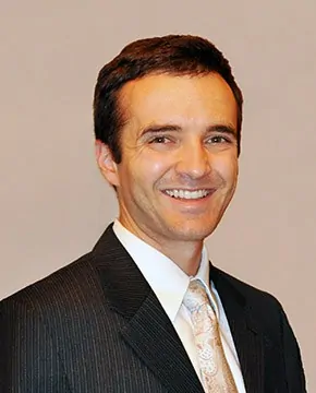
The Waste360 “40 Under 40” awards program recognizes inspiring and innovative professionals under the age of 40 whose work in the waste, recycling, and organics industry has made a significant contribution to the industry. Dave Hostetter focuses on designing landfill gas systems and landfill gas flare systems. Although still considered a young professional himself, he serves as a mentor to other engineers, providing guidance with hands-on design as well as professional guidance.
Dave is a LEED® Accredited Professional (LEED AP) and a Certified Energy Manager (CEM). He brings to SCS Engineers an abundance of expertise and fresh ideas. Dave has a keen eye for troubleshooting and diagnosing control system issues. He serves SCS clients wholeheartedly and goes out of his way to provide assistance as well as the expertise needed to make their day-to-day operations run as smoothly as possible. Dave has participated in a multitude of landfill gas and leachate system designs, including designs for blower and flare stations, wellfields, gas conveyance piping, leachate pumping systems, and groundwater extraction systems. His vast and varying experience, honest and hard-working approach to projects, and his positive attitude make him a respected resource within the firm.
Dave lives the SCS mission, and clients trust him for his honest and comprehensive approach to their challenges. Dave takes ownership of his work and puts in the time and effort to deliver excellent results and maintain a great relationship with his clients. “Dave Hostetter sets the example of how an honorable, dynamic, and experienced engineer should act at SCS,” said Paul Mandeville, Senior Vice President and Director of SCS’s offices on the east coast. “Dave serves as a model of what young professionals and students should strive to become in their professional and personal careers; we are very proud of him.”
Please join SCS in congratulating Dave Hostetter on his recent recognition by Waste360.
If you are buying or selling a property with a history of soil or groundwater contamination in Wisconsin, the state’s Department of Natural Resources requires vapor intrusion pathway screening. The screening is also necessary when buying or selling a property adjacent to a property with soil or groundwater contamination. Is this analysis necessary?
The screening is essential; vapors from contaminated soil or groundwater may transfer to indoor air, causing health risks. The vapors may or may not have an odor. Screen testing and analysis will determine their existence and the level of concentration. Most commonly levels are low, and no additional action is necessary. If beyond the threshold determined safe by your state, some mitigation may be required before purchase.
It is not a simple matter to apply an individual state’s current regulatory guidance to determine the need for vapor intrusion mitigation. The actual intrusion, or expected intrusion in the case of new buildings, is often overstated, and some regulatory agencies use screening values for indoor air chemical concentrations that are at or below levels commonly found in buildings. The slightest error in sampling technique can dramatically affect the resulting data.
SCS offers the full array of vapor intrusion services for residential, commercial, and industrial properties, and for developers, municipalities, lenders, attorneys, industrial facilities, tenants, landlords, and buyers and sellers of real property.
Contact SCS at 1-800-767-4727 or email us at .
Question about this blog, please email one of the authors Robert Langdon and Thomas Karwoski.
SCS has offices nationwide to serve our customers. To learn more about vapor mitigation, please visit the SCS website here: https://www.scsengineers.com/services/hazardous-waste-and-superfund/vapor-intrusion-mitigation-systems.
The Solid Waste Association of North America (SWANA) Applied Research Foundation released a report concluding that: a significant amount of additional food waste processing capacity will be required to achieve national, state, provincial, and local food waste diversion goals. The report also emphasizes the need for local decision-making in selecting and implementing those food waste diversion programs.
…a significant amount of additional food waste processing capacity will be required to achieve national, state, provincial, and local food waste diversion goals. The report also emphasizes the need for local decision-making in selecting and implementing those food waste diversion programs.
The report goes on to say that interest in recovering food waste from municipal solid waste is growing to meet goals established by the U.S. Environmental Protection Agency and U.S. Department of Agriculture, but many major metropolitan areas lack the infrastructure to manage the ability to meet the established goals. Two examples were cited:
Several states, including Massachusetts and Connecticut, condition their food waste diversion requirements on the ability of generators to access adequate capacity within a certain distance.
Speaking as SWANA’s Executive Director and CEO David Biderman stated:
We believe that Americans need to rethink how food is handled before it is considered waste, to divert it into programs to feed people, and to find other productive uses for food as food. Once it becomes waste, however, municipal decision-makers, working with their processing partners, need to determine how to best manage the material.

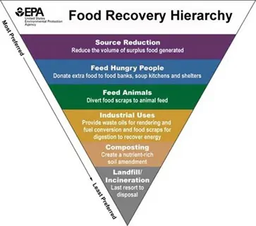
The SWANA report focuses on the effects of food recovery at the two lowest tiers of the hierarchy – composting and landfilling/incineration. The report concludes that food waste diverted from landfill operations has the potential to be processed at composting facilities. Then, going on to say that anaerobic digestion (AD) and co-digestion at wastewater treatment facilities are also likely destinations for diverted food waste.
Jeremy O’Brien, Director of the Applied Research Foundation, noted:
The food recovery hierarchy does not apply universally; an analysis of greenhouse gas impacts based on local data and conditions is needed to identify the best food scraps management options for a specific community.
The report encourages solid waste managers to perform a life cycle analysis of economic and environmental costs and benefits based on local needs, system capabilities, and data to identify the most effective ways to manage food waste at the local level.
SCS Engineers and SWANA are both long-time advocates for local decision-making in establishing programs to collect and manage municipal solid waste.
Related articles: