Landfill slopes that have reached final grades, or will receive waste in the distant future have maintenance challenges. Environmental elements continually affect surface conditions, and remedial work is required routinely to prevent negative outcomes of exposed slopes. Consider using a geomembrane temporary cap to address much of the maintenance. Here’s a list showing how the cap can help:
Landfill Maintenance Challenge
With Geomembrane Temporary Cap
The significant maintenance savings by using a temporary cap make the payoff period for the investment attractive. Based on my experience and site variations, the return on investment is usually three to six years. The period is considerably shorter if your landfill does not have a leachate disposal or treatment system, or deep injection well. The difference is the high cost to have the leachate hauled away.
Temporary caps potentially reduce routine maintenance work, leaving operation staff available for other tasks. The cap provides peace of mind that slopes remain in compliance; regulators don’t need to report non-compliance conditions of exposed slopes during inspection events.
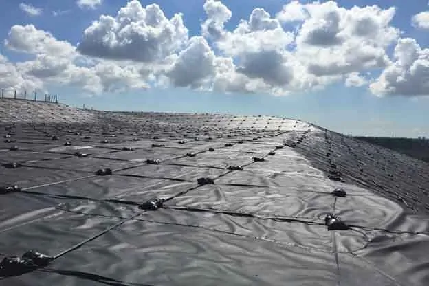
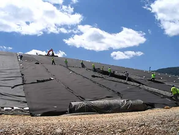
After completing 25 temporary cap projects in the U.S. Southeast alone, we highly recommend using a thick geomembrane. It’s tempting to try to save money using a thinner geomembrane, such as 12 mils or 20 mils, but these can damage more easily and will negatively affect your return. The majority of SCS clients chose to use the recommended 40 mils thick geomembrane, which will survive severe weather conditions.
Ballasting the geomembrane and using the right materials for ballasting is significantly important. We recommend using ultraviolet (UV) resistant rope and sandbags, a tried and true system. UV resistant straps are a decent replacement for ropes. Anchoring mechanisms are also important. We typically recommend using 4×4 treated wood posts at 10-ft spacing, installed in anchor trenches, and tied to ballasting ropes. Depending on the site and operator’s preference, the supporting architecture may be to lay the post horizontally, while tied to the ballasting ropes, at the bottom of the anchor trench buried in the anchor trench’s backfill material.
Over the years, landfill operators have experienced the savings and value that temporary caps bring to landfill operating budgets, and we’re placing more temporary caps every year. If considering this option, SCS can assist you by evaluating the slopes at your site for the caps. We’ll also prepare estimates for the purchase of material and installation costs and estimated time of recovery for your project.
About the Author: Ali Khatami, Ph.D., PE, LEP, CGC, is a Project Director and a Vice President of SCS Engineers. He is also our National Expert for Elevated Temperature Landfills, plus Landfill Design and Construction Quality Assurance. He has nearly 40 years of research and professional experience in mechanical, structural, and civil engineering.
Learn more at Landfill Engineering
Landfills are complex systems with many pipes for liquids and landfill gas running in many different directions. Some of these pipes are at the bottom of the landfill, such as leachate collections pipes, leachate toe drain pipes, pressure release pipes, etc. Other pipes are near the final cover system, either below or above, and closely interact with the final cover geosynthetics. Many of these are for control of landfill gas or leachate seeps at the landfill surface. Pipes may include vertical gas wells, horizontal gas wells, condensate sumps, condensate force main, compressed air lines to gas well pumps and condensate sumps, seep control sumps, electric conduits to condensate sumps and seep control sumps, leachate recirculation force main, stormwater downchutes, etc.
When pipe locations are near the final cover geosynthetics, below or above, or penetrating the final cover, design plans should show details of how the pipes or associated components interact with the final cover components. Lack of sufficient information may cause difficulties years later when scheduling the construction of the final cover. Most often, it becomes evident that many of the pipes constructed years earlier are too short for extending through the final cover.
Another aspect of piping and their interaction with the final cover is conflicts among different pipes, more specifically conflicts among gas pipes and liquid carrying pipes, in and near the final cover system. Liquid carrying pipes may include stormwater downchutes, rainwater toe drain pipes, and leachate toe drain pipes. Stormwater downchutes are usually large diameter pipes extending from the top of the landfill to the perimeter stormwater system. Rainwater toe drain pipes – pipes that receive water from the final cover geocomposite drainage layer, and leachate toe drain pipes – to collect leachate seeps below the final cover geomembrane, are co-located at terraces on slopes and the toe of the slope near the perimeter berm.
A few design considerations can be useful as guidelines during the preparation of design sets to address the relative position of these pipes and the final cover geosynthetics or to avoid conflict among pipes.
The complexity of landfills varies from site to site, and issues related to conflicts among gas and liquids pipes, and pipes and final cover geosynthetics vary depending on the geometry and other landfill features involved at each location. The best way to resolve conflicts before construction is to have a coordinated effort among parties involved in the design to discuss and find solutions to every conflict at the design stage.
About the Author: Ali Khatami, Ph.D., PE, LEP, CGC, is a Project Director and a Vice President of SCS Engineers. He is also our National Expert for Landfill Design and Construction Quality Assurance. He has nearly 40 years of research and professional experience in mechanical, structural, and civil engineering.
Learn more at Landfill Engineering
Corporate Headquarters