Thank you for your interest in Modern Landfill Design to Maximize Capital Investment Returns. We intend the blogs listed below to supplement the information covered or mentioned in the live session and video recording. Feel free to share the video and blog resources with others – we’ll protect your privacy!
As SCS employee-owners, we understand, better than most, that efficiencies create savings and value. Your Project Managers, Field Staff, and our presenters can answer specific questions or contact us at anytime. You can find our local professionals under the People tab and filter by specialty and office location.
Landfill Partial Final Covers and Associated Features Engineers weld the final cover geomembrane to the bottom lining system geomembrane for cases when there is a bottom lining system below the waste. The welding completely seals the landfill interior space from the outside environment and keeps regulated materials, such as waste, leachate, and gas, within the sealed system…
Knowledge of Landfill Sites and Efficacy of Conducting Due Diligence It is not unusual to see several different landfill designers providing services at a specific site over many years. Each landfill designer brings their preferences and designs …
Standard Coordinate Systems for Landfill Topographic Maps Landfill engineers rely heavily on topographic maps in their design work. Topographic maps present elevation contours, known as contour lines, for changes in the ground surface. Surveying companies create contour …
Familiarization with Site History before Design Work for Landfills Landfills are large and dynamic systems that can take several decades to develop. Unlike many other infrastructure projects with a beginning and an end to the construction of the …
Long-Term Performance of Landfill Final Covers There are several hundreds of Municipal Solid Waste (MSW) landfills in the United States. Many of these landfills are anticipated to remain active …
Elevated Temperature Conditions in Landfills: Sharing Innovative Designs and Strategies Landfill operators have known about elevated temperature conditions in landfills for nearly a decade. Some operators have already incurred numerous expenses to control adverse …
Temporary Caps – Becoming a No-Brainer for Landfills Landfill slopes that have reached final grade or will receive waste in the distant future have maintenance challenges. Environmental elements continually affect surface conditions, and remedial work is required routinely …
Final Cover System and Landfill Gas Piping – Design Considerations Landfills are complex systems with many pipes for liquids and landfill gas running in many different directions. Some of these pipes are at the bottom of the landfill, such as …
Landfill Leachate Seeps – Prepare Ahead to Avoid the Consequences Leachate seeps from relatively wet landfills are a fact of life for some operators. Leachate seeps increase in intensity and frequency after a storm, and you’re wondering, how many seeps …
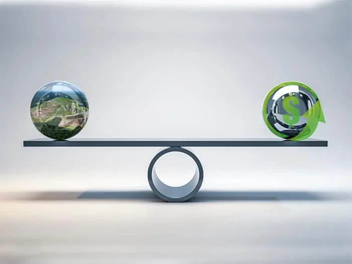
Landfill Airspace – Are You Maximizing Your Greatest Asset? Landfills, especially large regional landfills, are huge enterprises with many different operations ongoing daily. A landfill’s tangible assets are equipment, buildings, machinery, construction materials …
Emerging Design Concepts to Facilitate Flow of Liquids on Landfills It’s basically a circular hole with a gravel pipe in the middle, constructed at different stages of landfill filling operations, which enables water to flow through quickly while removing gas. The first tier is typically installed over 100-80 feet of waste, and the next one over another 100-80 feet of waste with structures that connect the tiers. “How many tiers are installed depends on waste thickness at different locations within the landfill. It can go up to four or five tiers,” he says.
Landfill Gas Header: Location and Benefits By continuing to design gas header construction on landfill slopes, all of the components end up on the landfill slope as well. You can imagine what type of complications the landfill operator will face since all of these components are in areas vulnerable to erosion, settlement, future filling or future construction. Additionally, any maintenance requiring digging and re-piping necessitates placing equipment on the landfill slope and disturbing the landfill slope surface for an extended period.
Gas Removal from Leachate Collection Pipe and Leachate Sump Keeping gas pressure low in and around the leachate collection pipe promotes the free flow of leachate through the geocomposite or granular medium drainage layer to the leachate collection pipe and improves leachate removal from the disposal cell. Using gas removal piping at leachate sumps is highly recommended for warm or elevated temperature landfills where efficient leachate removal from the leachate collection system is another means for controlling landfill temperatures…
Leachate Force Main Casing Pipe and Monitoring for Leaks Landfill operators may add a casing pipe to their leachate force main for additional environmental protection. Consequently, the leachate force main is entirely located inside a casing pipe where the …
Designing the Landfill Disposal Cell Base Slope with Consideration for Transmissivity Value One of the most important regulatory requirements on landfill bottom lining system drainage layer is that the maximum head of leachate over the liner should not exceed 1 ft. When …
Landfill Designers Play an Important Role in Landfill Safety Today’s landfill design professionals can help eliminate unsafe configurations and institute features that can proactively warn of and minimize hazards for operator and customer safety. Designers consider subgrade conditions, geotechnical …
Landfill Disposal Cell Base Slope Design When geonets and geocomposites entered the market, the unwritten consensus among solid waste engineers and regulators was that the maximum head of leachate at the base should not exceed the thickness of the geonet or geocomposite drainage layer. With that in mind, the reduction in transmissivity of geocomposite laid over steeper slopes can adversely impact the maximum leachate head over the liner…
Addressing High Gas Pressure Near the Bottom of Landfills The pipes are extended to outer limits of the cell and to the top of the perimeter berm where they connect to a vacuum source. These pipes will successfully remove excess gas pressures that may develop near the bottom lining system and prevent adverse impacts of the high pressures on the free flow of leachate through the bottom lining system drainage layer.
Vertical Drains in Landfills Offer More Efficient Leachate and Gas Collection Reducing Capital Investment Vertical drains help landfill liquids reaching the gas well gravel pack to flow to the leachate collection system at the bottom of the landfill; thus preventing watering out the gas wells. This sustainable alternative keeps gas production efficient and is environmentally sound, requiring less capital investment…
Shall We End the Herringbone’s 50-Year Reign in Landfill Design? Ali Khatami makes his case for the landfill chevron pattern. For at least the past 50 years, our industry has referred …
Innovative Landfill Design Technologies and Industry Pioneers SCS Engineers is a leading environmental consulting and contracting firm with over 50 years of expertise in designing, permitting, constructing, and operating landfills. The firm is a pioneering force …
State regulatory agencies normally require landfill slopes reaching final grades to close within a certain period. This requirement leads to closing landfill slopes in phases, normally referred to as partial closure. Generally, partial closures start from the bottom of the landfill slope up to a certain elevation, with geosynthetics in the final cover temporarily anchored along the partial closure’s sides and upper boundary. Engineers propose different designs for securing the lower boundary of partial closures at the bottom of the landfill slope. Some engineers propose an anchor trench outside the bottom lining system anchor trench to secure the final cover geosynthetics. Others specify welding the cover geomembrane to the bottom lining system geomembrane.
Experience with anchor trenches at the bottom of the landfill slope for the final cover geosynthetics has not been positive because of these issues:
To eliminate the issues above, engineers weld the final cover geomembrane to the bottom lining system geomembrane for cases when there is a bottom lining system below the waste. The welding completely seals the landfill interior space from the outside environment and keeps regulated materials, such as waste, leachate, and gas, within the sealed system. Of course, the engineer should design proper means to address these behind the sealed system; designs may include:
Leachate toe drain system is a concept originally developed by SCS and incorporated into landfill final cover designs over the past 20 years. Unfortunately, many solid waste engineers are unaware of the need for LTDS, so their designs lack this important feature. LTDS saves a tremendous amount of repair money in the long run by avoiding complications for landfill operators.
A rainwater toe drain system removes water that moves laterally within the final cover geocomposite toward the slope’s bottom. The RTDS includes a perforated HDPE pipe encased in gravel and wrapped in geotextile. Also, install the RTDS on terraces along the depression on the interior side of the terrace. Along the landfill slope’s bottom, position the RTDS behind a HDPE flap welded to the final cover geomembrane. The RTDS is sloping with high and low points along the RTDS alignment. Lateral drain pipes located at low points remove water from the RTDS to the perimeter ditches.
Other designs involving extending the geocomposite to daylight at the slope surface cause problem such as those listed below:
Similar issues can also occur at the outlet of such systems on landfill terraces, making the RTDS a superior design.
About the Author:
 Ali Khatami, Ph.D., PE, LEP, CGC, is a Project Director and a Vice President of SCS Engineers. He is also our National Expert for Landfill Design, Construction Quality Assurance, and Elevated Temperature Landfills. He has over 40 years of research and professional experience in mechanical, structural, and civil engineering.
Corporate Headquarters