Do you have NSPS or EG sites per the new definitions of “new” and “existing”?
Does your EG site have any upcoming planned or permitted expansions, or will it be commencing construction on an expansion permitted after July 17, 2014?
Will you need to submit/resubmit Design Capacity and NMOC reports to establish your sites status as subject to the new NSPS? Over, or under 34 Mg/year of NMOCs?
Are you a candidate for Tier 4? In the closed landfill subcategory?
For EG sites contact the SCS state representative by sending a request to
SCS Engineers will be publishing Pat Sullivan’s Technical Bulletin Summary of Final NSPS/EG Rules for Landfills as soon as it is published in the federal register. Meanwhile, please contact your SCS Project Manager or for answers to your questions or advice. Follow SCS Engineers on your favorite social media site or check our events for new presentations, publications, and webinars explaining the rules in more detail.
Jeff Marshall, PE, SCS Engineers will be presenting the topic of Hydrogen Sulfide Issues at CCR and MSW Co-Disposal Sites during the EREF and NWRA sponsored Coal Ash Management Forum in July.
The co-disposal of municipal solid waste and coal combustion residuals – particularly flue gas desulfurization (FGD) material – poses a significant concern regarding the generation of hydrogen sulfide gas. Hydrogen sulfide has an exceptionally low odor threshold, and can pose serious health concerns at higher concentrations. This presentation will identify the biological, chemical and physical conditions necessary for FGD decomposition and hydrogen sulfide generation. Recommendations for reducing the potential for FGD decomposition at co-disposal facilities will be presented. Technologies for the removal and treatment of hydrogen sulfide from landfill gas will also be addressed.
Jeff Marshall, PE, is a Vice President of SCS Engineers and the Practice Leader for Environmental Services in the Mid-Atlantic region. He also serves as the SCS National Expert for Innovative Technologies. He has a diversified background in environmental engineering and management, with emphasis on the chemical and human health aspects of hazardous materials and wastes. Mr. Marshall’s experience with hydrogen sulfide, odors, sulfate decomposition in landfills, and ash issues includes scores of projects dating back to the 1980s.
SCS Coal Combustion Residual Services
Glass accounts for almost 5% of the municipal solid waste stream; state and local agencies have set ambitious zero waste goals; many agencies are not ready to give up on glass recycling. How do they manage to keep their programs viable despite the cost of processing, transportation, and the challenge of cross contamination?
Sustainable Solid Waste Managment Planning and Programs
The drainage layers of landfill final covers normally go through a rigorous flow capacity evaluation. This evaluation is necessary to ensure that the volume of water reaching the drainage layer due to percolation of precipitation water through the final cover upper soil layer will not overwhelm the drainage layer in its flow path. If the flow volume in the geocomposite drainage layer is greater than the capacity of the drainage layer, water will exit the geocomposite and enter the overlying soil. The water entering the soil layer can easily saturate the lower portion of the soil layer, which will affect the stability of the slope. The geocomposite should always be designed to have a flow capacity greater than the flow rate of water running through it.
Concave areas of a landfill slope experience flow patterns quite different from slopes that go straight down. Slopes with concaved geometry have an unequal crest and toe lines – the toe line being smaller than the crest line. As a result, the width of the concaved slope decreases as the distance from the crest line increases in the downward direction. The narrowest width of the concaved slope is at the toe of the slope. The drainage layer on the slope experiences the same width change from the crest line to the toe line. This means that the overall width of the channels that carry water within the geocomposite drainage layer decreases toward the toe line, and, therefore, the depth of water in the channels increases. This phenomenon is referred to as flow convergence, and the convergence is toward the vertical centerline of the concaved slope. The flow convergence may be significant enough to increase the water depth in the geocomposite in the vicinity of the vertical centerline of the slope to greater than the thickness of the geocomposite. That, in turn, forces water out of the geocomposite and into the overlying soil, which may result in slope stability problems.
To complement the geocomposite flow capacity along the vertical centerline of the concaved slope in order to accommodate the higher water flow rates in the system, a pipe-gravel-geotextile (a burrito) may be constructed along the vertical centerline of the slope. The burrito, which would be positioned directly over the geocomposite drainage layer, increases the flow capacity of the system at and in the vicinity of the vertical centerline of the concaved slope. The burrito will receive water from the geocomposite where the water depth exceeds the geocomposite thickness. The burrito will be connected to the toe drain system at the toe of the slope, and water in the burrito will be discharged to the toe drain. The water in the toe drain, in turn, leaves the final cover through lateral drain pipes at regular intervals.
It should be noted that not every concaved slope requires a burrito. Some concaved slopes may be fairly wide, and the convergence of water inside the geocomposite may not be significant enough to cause the depth of water to exceed the geocomposite thickness. But, if the concavity of the slope is significant, a severe convergence of water in the geocomposite drainage layer is more likely. In that case, a burrito along the vertical centerline of the concaved slope is highly recommended.
A cautionary construction related note seems to be appropriate at this point. During construction, extra care should be taken to ensure that all geocomposite panels within the boundary of the concaved slope run such that the machine direction of the panels follows a path from the top toward the bottom of the slope. If some geocomposite panels are installed with the machine direction running across the slope width, significant turbulence in the flow will be created at the point where panels running in one direction transition to the panels running in the other direction. The turbulence will reduce the flow capacity of the geocomposite.
If you are planning to install a final cover over a portion of the slope that has concaved geometry and you want your final cover design to properly address flow volumes in the geocomposite drainage layer, please contact us. SCS Engineers has extensive experience with these types of circumstances, and we will gladly review your case and make recommendations. Learn more here.
If you have comments or questions about this article, please contact Dr. Ali Khatami.
Ali Khatami, Ph.D., PE, LEP, CGC, is a Project Director and a Vice President of SCS Engineers. He is also our National Expert for Landfill Design and Construction Quality Assurance. He has nearly 40 years of research and professional experience in mechanical, structural, and civil engineering.
Dr. Khatami has acquired extensive experience and knowledge in the areas of geology, hydrogeology, hydrology, hydraulics, construction methods, material science, construction quality assurance (CQA), and stability of earth systems. Dr. Khatami has applied this experience in the siting of numerous landfills and the remediation of hazardous waste contaminated sites.
Dr. Khatami has been involved in the design and permitting of civil and environmental projects such as surface water management systems, drainage structures, municipal solid waste landfills, hazardous solid waste landfills, low-level radioactive waste landfills, leachate and wastewater conveyance and treatment systems. He is also involved in the design of gas management systems, hazardous waste impoundments, storage tank systems, waste tire processing facilities, composting facilities, material recovery facilities, landfill gas collection and disposal systems, leachate evaporator systems, and liquid impoundment floating covers.
As more and more landfill closure projects were built using geomembranes as the final cover barrier layer over the past 20 years, the issue of handling water in the final cover drainage layer became more prominent. Precipitation on closed portions of a landfill leaves the landfill basin in three ways: (1) runoff; (2) percolating into the final cover upper soil layer and then evaporating back out into the atmosphere by evapotranspiration; and (3) percolating into the final cover upper soil layer and reaching the final cover drainage layer, flowing through the drainage layer to the bottom of the landfill slope, and leaving the landfill basin through discharge points to the landfill perimeter ditch. Addressing the runoff component is relatively straightforward because for decades engineers have been designing various types of conveyance systems to handle surface water runoff. Mother Nature takes care of the second component.
The third component, however, took many years to be engineered properly. SCS developed one of the best-engineered systems over 18 years ago and perfected the design over the following five years. The perfected design has been incorporated into the permits of many landfills and implemented at many closure construction events. As a commitment to the efficiency of the design, SCS has been monitoring the performance of many of these closure projects during rain events to gather data and ensure that nothing unexpected occurs during the more severe storm events.
SCS’s system involves a perforated collection pipe embedded in gravel, wrapped in geotextile, and placed in a depression created by a geomembrane flap near the bottom of the slope. The geomembrane flap is welded to the final cover geomembrane and supported in a depressed shape by the upper soil layer of the final cover system. The drainage layer geocomposite ends at the bottom of the depression, delivering the water in the geocomposite into the pipe-gravel-geotextile positioned inside the depression. Installation of the geomembrane flap is at a sloping grade; therefore, the collection pipe ends up sloping toward a low point where a drain pipe that is perpendicular to the perforated pipe takes the water out of the depression and delivers it to the landfill perimeter ditch. The system is fairly easy to install and almost guarantees proper removal of water from the final cover drainage layer. Although other engineers have designed many varieties of such systems, the SCS system has a proven track record with no glitches or side effects at the bottom of the landfill slope.
Some other systems, because of the inherent shortcomings in the design, either don’t remove all of the water from the geocomposite drainage layer, or they clog at the discharge point. Sometimes the water coming through the system adversely affects other landfill components, such as the perimeter berm integrity. Additionally, complexities during construction of the system can conflict with the storm water down chute pipes or landfill gas pipes that may exist above the cover system geomembrane.
———————
In addition to writing the SCS Engineers blog series SCS Advice from the Field, Dr. Khatami speaks about SCS blog topics at SWANA national and local chapter conferences. His webinar Design Leachate Collection Pipes to Eliminate Clogging of Geotextiles will be presented on June 29, 2016. Use the links below to learn more about Dr. Khatami’s advanced landfill designs which last longer and help prevent common operational challenges over time.
How to Manage Leachate Seeps Below the Final Landfill Geomembrane Cover
Recommendations for Jet Cleaning Leachate Collection Pipes
Avoid Geotextile Clogging of Leachate Collection Pipes
Ali Khatami, Ph.D., PE, LEP, CGC, is a Project Director and a Vice President of SCS Engineers. He is also our National Expert for Landfill Design and Construction Quality Assurance. He has nearly 40 years of research and professional experience in mechanical, structural, and civil engineering.
Dr. Khatami has acquired extensive experience and knowledge in the areas of geology, hydrogeology, hydrology, hydraulics, construction methods, material science, construction quality assurance (CQA), and stability of earth systems. Dr. Khatami has applied this experience in the siting of numerous landfills and the remediation of hazardous waste contaminated sites.
Dr. Khatami has been involved in the design and permitting of civil and environmental projects such as surface water management systems, drainage structures, municipal solid waste landfills, hazardous solid waste landfills, low-level radioactive waste landfills, leachate and wastewater conveyance and treatment systems. He is also involved in the design of gas management systems, hazardous waste impoundments, storage tank systems, waste tire processing facilities, composting facilities, material recovery facilities, landfill gas collection and disposal systems, leachate evaporator systems, and liquid impoundment floating covers.
If you are looking to design a final cover for your landfill, please contact SCS. We will review your particular needs and the existing conditions at your facility and will recommend a proper design that suits your site conditions. SCS will also provide you with construction recommendations and an estimate for construction of the system. Furthermore, SCS will gladly incorporate the final design into your facility permit and prepare construction drawings for implementation of the system.
The Solid Waste Association of North America (SWANA) Applied Research Foundation released a report concluding that: a significant amount of additional food waste processing capacity will be required to achieve national, state, provincial, and local food waste diversion goals. The report also emphasizes the need for local decision-making in selecting and implementing those food waste diversion programs.
…a significant amount of additional food waste processing capacity will be required to achieve national, state, provincial, and local food waste diversion goals. The report also emphasizes the need for local decision-making in selecting and implementing those food waste diversion programs.
The report goes on to say that interest in recovering food waste from municipal solid waste is growing to meet goals established by the U.S. Environmental Protection Agency and U.S. Department of Agriculture, but many major metropolitan areas lack the infrastructure to manage the ability to meet the established goals. Two examples were cited:
Several states, including Massachusetts and Connecticut, condition their food waste diversion requirements on the ability of generators to access adequate capacity within a certain distance.
Speaking as SWANA’s Executive Director and CEO David Biderman stated:
We believe that Americans need to rethink how food is handled before it is considered waste, to divert it into programs to feed people, and to find other productive uses for food as food. Once it becomes waste, however, municipal decision-makers, working with their processing partners, need to determine how to best manage the material.
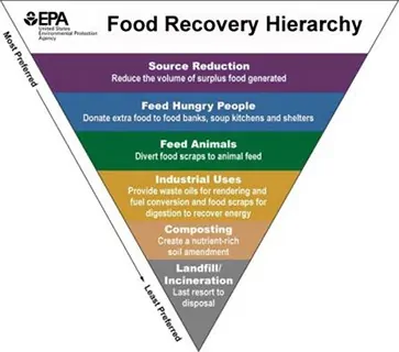
The SWANA report focuses on the effects of food recovery at the two lowest tiers of the hierarchy – composting and landfilling/incineration. The report concludes that food waste diverted from landfill operations has the potential to be processed at composting facilities. Then, going on to say that anaerobic digestion (AD) and co-digestion at wastewater treatment facilities are also likely destinations for diverted food waste.
Jeremy O’Brien, Director of the Applied Research Foundation, noted:
The food recovery hierarchy does not apply universally; an analysis of greenhouse gas impacts based on local data and conditions is needed to identify the best food scraps management options for a specific community.
The report encourages solid waste managers to perform a life cycle analysis of economic and environmental costs and benefits based on local needs, system capabilities, and data to identify the most effective ways to manage food waste at the local level.
SCS Engineers and SWANA are both long-time advocates for local decision-making in establishing programs to collect and manage municipal solid waste.
Related articles:
The benefits of implementing these cleaning recommendations for leachate collection pipes will help keep the pipes clean and fully functioning; helping landfill operators prevent the potentially serious complications of clogged pipes and immovable leachate.
By Dr. Ali Khatami, P.E., SCS Engineers
Some states require that leachate collection pipes be cleaned with high-pressure jets on a regular basis (for example, every ten years or even more frequently); however, the rules don’t clarify or set forth the specific conditions under which the jet cleaning should be performed. Some landfills have undertaken jet cleaning while the pipes are partially or fully submerged in leachate above the liner. Unfortunately, jetting under water may drastically reduce the effectiveness of the pressurized jet, resulting in a pipe that is not cleaned properly. This is even more important when the jetting is intended to remove biological growth on the pipe walls and in the perforation openings.
In addition, many states do not require videotaping the pipe after jetting. Videotaping is the best way to verify that the pipe was cleaned successfully. If the leachate collection pipes are not properly cleaned, then over a period of 20 years or so, they can be adversely impacted by severe biological growth and buildup in the pipe perforations to the point that liquid can no longer enter the pipe.
Another shortcoming is that the rules do not specifically require that the riser pipes (where the submersible pumps are located) be cleaned or videotaped. Therefore, due to the added costs, some landfill operators may not clean the riser pipes as part of the required cleaning events, or they may delay such cleanings for an extended period. This can prevent leachate from flowing into the riser with the direct and serious consequence that leachate cannot be removed from the sump.
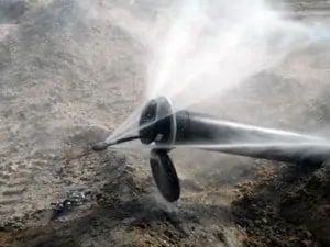
Another issue to consider is that pressurized jet cleaning procedures do not necessarily push the solids that separate from the pipe wall out of the pipe inlet opening through which the cleaning nozzle entered the pipe. As a result, these solids flow out of the pipe and into the gravel bedding on the outside of the pipe, and can potentially clog the void within the gravel pack around the pipe or in the sump. Clogging the sump gravel can mean reduced flow capacity from the leachate collection pipe to the riser pipe and the submersible pumps.
To resolve these issues, SCS recommends the following:
The benefits of implementing these recommendations will help keep the pipes clean and fully functioning. These suggestions help prevent potentially serious complications that the landfill operator may have to address if the pipes are clogged and leachate cannot be removed.
Questions? Contact Ali Khatami, PhD, PE, LEP, CGC, is a Project Director and a Vice President of SCS Engineers. He is also our National Expert for Landfill Design and Construction Quality Assurance. He has nearly 40 years of research and professional experience in mechanical, structural, and civil engineering. Dr. Khatami has acquired extensive experience and knowledge in the areas of geology, hydrogeology, hydrology, hydraulics, construction methods, material science, construction quality assurance (CQA), and stability of earth systems. Dr. Khatami has applied this experience in the siting of numerous landfills and the remediation of hazardous waste contaminated sites.
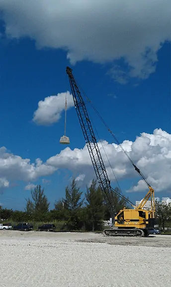
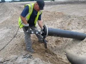
Dynamic compaction is a construction technique that increases the density of soil/waste deposits by dropping a heavy weight at regular intervals to consolidate and improve the geotechnical characteristics of the deposit so that it can be suitable for redevelopment. This construction technique can be used to transform otherwise undevelopable property, such as old landfill areas, into developable property.
Most soil types can be improved by dynamic compaction; the method is particularly well suited to non-organic, irregular fill, where variable characteristics such as solid wastes are present. Field conditions and several other parameters are considered when designing and implementing dynamic compaction programs to keep costs in line. The primary considerations include, but are not limited to, waste delineation, distance from the ground surface to ground water, waste thickness, minimum energy, and selection of dynamic compaction parameters.
The following factors and associated costs should be evaluated if dynamic compaction is to be considered:
Major change orders and environmental impacts can be expected if the plan does not address these factors.
If you decide to consider dynamic compaction in your redevelopment project, having onsite construction quality assurance monitoring during the process is important. CQA monitoring will verify that the work is implemented as designed and permitted, and that proper techniques are used to make sure the proper distribution of energy into the ground is taking place. The CQA monitor will also check to see that the final configuration of the fill is achieved, a safe working environment is maintained., and that ground vibrations are monitored near adjacent structures to to prevent structural damage.
For developments involving construction of buildings over a dynamically compacted areas, a combustible gas barrier layer is generally required below the building footprint to safely collect and vent subsurface combustible gases (i.e., typically methane) to the environment. Construction costs associated with a combustible gas barrier layer should include the following:
In summary, dynamic compaction is a proven geotechnical construction engineering method that can be used to improve certain landfill areas to support redevelopment. SCS Engineers has completed many projects of this nature and is ready to serve and help to bring your project in service.
Related Article
Pursuing Dynamic Compaction, by Ali Khatami, Ph.D., Bruce Clark, P.E., and Myles Clewner, L.E.P., Waste Age
Sample Case Studies
Environmental Due Diligence – Procacci Site, Sweetwater, Florida
Landfill Engineering and Consulting – Medley Landfill, Miami-Dade County, Florida
Landfill Site Redevelopment for the City of Industry, California
Ali Khatami, PhD, PE, LEP, CGC, is a Project Director and a Vice President of SCS Engineers. He is also our National Expert for Landfill Design and Construction Quality Assurance. He has nearly 40 years of research and professional experience in mechanical, structural, and civil engineering.
Dr. Khatami has acquired extensive experience and knowledge in the areas of geology, hydrogeology, hydrology, hydraulics, construction methods, material science, construction quality assurance (CQA), and stability of earth systems. Dr. Khatami has applied this experience in the siting of numerous landfills and the remediation of hazardous waste contaminated sites.
Dr. Khatami has been involved in the design and permitting of civil/environmental projects such as surface water management systems, drainage structures, municipal solid waste landfills, hazardous solid waste landfills, low-level radioactive waste landfills, leachate and wastewater conveyance and treatment systems. He has also been involved with the design of gas management systems, hazardous waste impoundments, storage tank systems, waste tire processing facilities, composting facilities, material recovery facilities, landfill gas collection and disposal systems, leachate evaporator systems, and liquid impoundment floating covers.

Have you ever found in the sleeve or the pocket of a new shirt the “Inspected By…” piece of paper? You probably don’t think twice about it. You simply look at it and throw it away. However, if you were to think about it, what might the process be to inspect the garment? To be sure the sleeves are the same length, or the collar is sewn on correctly, or that it has all the buttons. That tag is intended to signify that the product was reviewed and has met its required standards to be placed in service.
Ever wonder if anybody reviews the bottom of a landfill? When is it ready to be placed in service?
When I was a kid, a landfill was, for the most part, a hole in the ground filled with trash. Well, we still dig a hole, but since the early 1990’s, municipal solid waste landfills (MSWLF) require a containment system on the bottom and sides of the landfill beneath the waste. These containment systems, i.e. liner systems, are designed to protect human health and the environment by serving as a barrier between the waste and liquid in the landfill from the soil and groundwater outside the landfill. These liner systems are typically constructed of compacted clay liners and geosynthetic materials which are documented and inspected to ensure the liner system was built in accordance with the permit requirements and its overall purpose of protecting the environment.
The landfill liner inspection process is usually called Construction Quality Assurance (CQA) and is an important and integral component of protecting the environment. CQA is generally performed by a third party firm to provide an unbiased evaluation of the liner construction independent of the owner or the contractor.
SCS provides Landfill CQA services across the country. We have proven, experienced field staff that observe, document and test specific physical properties of the soil liner and geosynthetics. Our engineers are experienced and licensed to certify that the liner was built in accordance with the permit requirements.
Landfill CQA is not limited to the liner system. SCS provided CQA for final cover systems, leachate forcemain systems, and methane extraction systems.
If you are wondering more about landfill CQA or have a need for your facility, give us a call. We’d be happy to discuss in more detail and assist with your project. SCS is ready to serve, and help to bring your project in service.
Learn more about Jeff Reed and Construction Quality Assurance services at SCS, or see a matrix of CQA projects completed.
Contact Jeff Reed
DDC Journal recently published an interesting article by Pat Sullivan, “Developing power plants that reduce environmental impacts.” http://viewer.zmags.com/publication/097d62a6#/097d62a6/24
Pat Sullivan, BCES, CPP, REPA, is a Senior Vice President of SCS Engineers and our National Expert on the Landfill Clean Air Act and the New Source Performance Standard (NSPS). Mr. Sullivan has over 25 years of environmental engineering experience, specializing in solid and hazardous waste-related issues.
Corporate Headquarters