
In our newest SCS Advice from the Field, Ali Khatami makes his case for the landfill chevron pattern…
For at least the past 50 years, our industry has referred to the design pattern for the bottom of landfill cells as herringbone. But, it’s time to break the long-standing herringbone reign and give credit to the true holder of the crown: the chevron pattern. A chevron pattern visualizes the actual geometry used by landfill designers over the decades.
The schematic views of both patterns are shown below:
![]()
Now, here’s a sketch of a landfill single-cell design:
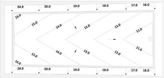
Note the cell base area with elevation contours that resemble the chevron pattern, with the leachate collection pipe located along the centerline of the cell. The cell base area is sloping toward the leachate collection pipe to convey landfill leachate at the base to the pipe, then the pipe conveys the leachate to the leachate sump located at the low end of the pipe. The pattern at the base can easily be duplicated in either direction of the cell area, developing a multi-cell design resembling the chevron pattern shown above.
In this case, the straight lines connect the low points (representing leachate collection pipes) and the high points (representing the divider berms separating adjacent cells). The zig-zag lines in the pattern remind landfill engineers of the elevation contours for the landfill bottom design geometry.
Meanwhile, with the herringbone pattern, the adjacent “tiles” or rectangular shapes are in a perpendicular position to each other and do not resemble the zig-zag lines in the chevron pattern. The herringbone pattern cannot be representative of the elevation contours, leachate collection pipes, and the boundary lines between adjacent cells like the chevron pattern. Additionally, the angle of line segments in the zig-zag in the chevron pattern can vary to any desirable value, which allows representation of changes to the disposal cell base slope (an important parameter in landfill design). On the contrary, the tile position in the herringbone pattern has to maintain perpendicular angles throughout and therefore it loses the ability to represent various base slopes.
One may draw lines along interface boundaries of the herringbone features and come up with the chevron pattern. But why stretch the truth when the chevron is already clearly the pattern? It is not apparent how or why the herringbone association took hold in the first place, but it’s about time that changed.
Admittedly, it took nearly four years to scientifically support the validity of the Special Relativity Theory from the time it was published by Albert Einstein in 1916. And it took nearly 50 years to physically detect the existence of Higgs boson particle from the time it was theorized by Peter Higgs in 1964. So, I suppose we can wait for formal recognition of chevron designation for landfill design.
Why such a big deal!?
The chevron validation may be insignificant compared to the scientific validations of Einstein’s and Higgs’ work. For landfill engineers, attune to details, it could be considered big because anything new, and more accurate in the landfill design field is a cheering matter!
Throughout the history of science, new findings supported by scientific evidence have replaced prior theories or concepts when progress is desired. Change of the pattern association, in this case, may not qualify as a scientific finding; however, it is a clear and noteworthy correction to what landfill engineers have been using over the past many years.
About the Author:
 Ali Khatami, Ph.D., PE, LEP, CGC, is a Project Director and a Vice President of SCS Engineers. He is also our National Expert for Landfill Design, Construction Quality Assurance, and Elevated Temperature Landfills. He has over 40 years of research and professional experience in mechanical, structural, and civil engineering.
I read your informative blog regarding recommendations for jet cleaning leachate collection pipes. I have a question.
QUESTION: Say a landfill only has access to one end of a leachate pipe. This would be a situation where a new cell was built, where the uphill side of the cell butts up against an existing, pre-subtitle D cell with no leachate collection pipe. In other words, the uphill side of the new leachate pipe simply terminates rather than tie into an existing pipe.
To add to the issue, no vertical cleanout/riser pipe was installed on the uphill end (as this may impede waste operations in the area). There are of course riser and cleanout pipes and a sump on the downhill side for normal leachate collection. I would imagine that pumping water from the accessible side would push out any solids through the perforations into the leachate aggregate bedding, and may cause clogging there.
Is it possible, or reasonable, to flush this new leachate line?
ANSWER: There is always a possibility that a portion of dislodged material from the interior walls of the pipe will pass through pipe perforations and enter the gravel bedding around the pipe. However, due to the pipe slope, the great majority of the separated material flows down the pipe to the lowest point where it can be removed using a vac-truck.
Keep in mind also that, it’s true that leachate can partially flow through the bedding gravel toward the sump, but the role of the gravel is primarily protecting the pipe against compressive loads of waste above. Partial clogging of gravel around the pipe should not be considered as a malfunction of the system. Partial clogging of gravel normally may occur near the bottom portion of the gravel pack, which still allows leachate flow through gravel to pipe perforations above any clogged zone below.
In several instances, when a portion of a leachate collection pipe was opened up after being in service for a while, it did not support the idea of a clogged zone in the gravel pack. What was observed, included discolored gravel due to fine particles settling (from filtered leachate through geotextile) on gravel particles and a bit of the same particles near the bottom of the gravel pack.
I’ve never observed severe clogging of the gravel pack.
Thanks for your interest in the subject, and please stay in touch with any other questions. SCS freely shares best practices and advice within our industry; email us at
About the Author: Ali Khatami, PhD, PE, LEP, CGC, is a Project Director and a Vice President of SCS Engineers. He is also our National Expert for Landfill Design and Construction Quality Assurance. He has over 40 years of research and professional experience in mechanical, structural, and civil engineering.
Survivability of leachate collection pipes depends upon the gravel placed on all sides of the pipe. Proper placement of gravel around the pipe and the granular soil material over the completed pipe/gravel/geotextile burrito is of significant importance in the protection of the leachate collection pipe.
Read the article by Dr. Ali Khatami here.
SCS Advice from the Field is a collection of blogs, articles, and white papers written by SCS professionals like Dr. Khatami. Search “advice from the field” to browse all of the topics.

As more and more landfill closure projects were built using geomembranes as the final cover barrier layer over the past 20 years, the issue of handling water in the final cover drainage layer became more prominent. Precipitation on closed portions of a landfill leaves the landfill basin in three ways: (1) runoff; (2) percolating into the final cover upper soil layer and then evaporating back out into the atmosphere by evapotranspiration; and (3) percolating into the final cover upper soil layer and reaching the final cover drainage layer, flowing through the drainage layer to the bottom of the landfill slope, and leaving the landfill basin through discharge points to the landfill perimeter ditch. Addressing the runoff component is relatively straightforward because for decades engineers have been designing various types of conveyance systems to handle surface water runoff. Mother Nature takes care of the second component.
The third component, however, took many years to be engineered properly. SCS developed one of the best-engineered systems over 18 years ago and perfected the design over the following five years. The perfected design has been incorporated into the permits of many landfills and implemented at many closure construction events. As a commitment to the efficiency of the design, SCS has been monitoring the performance of many of these closure projects during rain events to gather data and ensure that nothing unexpected occurs during the more severe storm events.
SCS’s system involves a perforated collection pipe embedded in gravel, wrapped in geotextile, and placed in a depression created by a geomembrane flap near the bottom of the slope. The geomembrane flap is welded to the final cover geomembrane and supported in a depressed shape by the upper soil layer of the final cover system. The drainage layer geocomposite ends at the bottom of the depression, delivering the water in the geocomposite into the pipe-gravel-geotextile positioned inside the depression. Installation of the geomembrane flap is at a sloping grade; therefore, the collection pipe ends up sloping toward a low point where a drain pipe that is perpendicular to the perforated pipe takes the water out of the depression and delivers it to the landfill perimeter ditch. The system is fairly easy to install and almost guarantees proper removal of water from the final cover drainage layer. Although other engineers have designed many varieties of such systems, the SCS system has a proven track record with no glitches or side effects at the bottom of the landfill slope.
Some other systems, because of the inherent shortcomings in the design, either don’t remove all of the water from the geocomposite drainage layer, or they clog at the discharge point. Sometimes the water coming through the system adversely affects other landfill components, such as the perimeter berm integrity. Additionally, complexities during construction of the system can conflict with the storm water down chute pipes or landfill gas pipes that may exist above the cover system geomembrane.
———————
In addition to writing the SCS Engineers blog series SCS Advice from the Field, Dr. Khatami speaks about SCS blog topics at SWANA national and local chapter conferences. His webinar Design Leachate Collection Pipes to Eliminate Clogging of Geotextiles will be presented on June 29, 2016. Use the links below to learn more about Dr. Khatami’s advanced landfill designs which last longer and help prevent common operational challenges over time.
How to Manage Leachate Seeps Below the Final Landfill Geomembrane Cover
Recommendations for Jet Cleaning Leachate Collection Pipes
Avoid Geotextile Clogging of Leachate Collection Pipes
Ali Khatami, Ph.D., PE, LEP, CGC, is a Project Director and a Vice President of SCS Engineers. He is also our National Expert for Landfill Design and Construction Quality Assurance. He has nearly 40 years of research and professional experience in mechanical, structural, and civil engineering.
Dr. Khatami has acquired extensive experience and knowledge in the areas of geology, hydrogeology, hydrology, hydraulics, construction methods, material science, construction quality assurance (CQA), and stability of earth systems. Dr. Khatami has applied this experience in the siting of numerous landfills and the remediation of hazardous waste contaminated sites.
Dr. Khatami has been involved in the design and permitting of civil and environmental projects such as surface water management systems, drainage structures, municipal solid waste landfills, hazardous solid waste landfills, low-level radioactive waste landfills, leachate and wastewater conveyance and treatment systems. He is also involved in the design of gas management systems, hazardous waste impoundments, storage tank systems, waste tire processing facilities, composting facilities, material recovery facilities, landfill gas collection and disposal systems, leachate evaporator systems, and liquid impoundment floating covers.
If you are looking to design a final cover for your landfill, please contact SCS. We will review your particular needs and the existing conditions at your facility and will recommend a proper design that suits your site conditions. SCS will also provide you with construction recommendations and an estimate for construction of the system. Furthermore, SCS will gladly incorporate the final design into your facility permit and prepare construction drawings for implementation of the system.
Corporate Headquarters