
In our newest SCS Advice from the Field, Ali Khatami makes his case for the landfill chevron pattern…
For at least the past 50 years, our industry has referred to the design pattern for the bottom of landfill cells as herringbone. But, it’s time to break the long-standing herringbone reign and give credit to the true holder of the crown: the chevron pattern. A chevron pattern visualizes the actual geometry used by landfill designers over the decades.
The schematic views of both patterns are shown below:
![]()
Now, here’s a sketch of a landfill single-cell design:
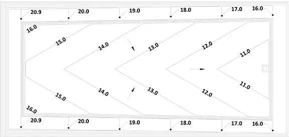
Note the cell base area with elevation contours that resemble the chevron pattern, with the leachate collection pipe located along the centerline of the cell. The cell base area is sloping toward the leachate collection pipe to convey landfill leachate at the base to the pipe, then the pipe conveys the leachate to the leachate sump located at the low end of the pipe. The pattern at the base can easily be duplicated in either direction of the cell area, developing a multi-cell design resembling the chevron pattern shown above.
In this case, the straight lines connect the low points (representing leachate collection pipes) and the high points (representing the divider berms separating adjacent cells). The zig-zag lines in the pattern remind landfill engineers of the elevation contours for the landfill bottom design geometry.
Meanwhile, with the herringbone pattern, the adjacent “tiles” or rectangular shapes are in a perpendicular position to each other and do not resemble the zig-zag lines in the chevron pattern. The herringbone pattern cannot be representative of the elevation contours, leachate collection pipes, and the boundary lines between adjacent cells like the chevron pattern. Additionally, the angle of line segments in the zig-zag in the chevron pattern can vary to any desirable value, which allows representation of changes to the disposal cell base slope (an important parameter in landfill design). On the contrary, the tile position in the herringbone pattern has to maintain perpendicular angles throughout and therefore it loses the ability to represent various base slopes.
One may draw lines along interface boundaries of the herringbone features and come up with the chevron pattern. But why stretch the truth when the chevron is already clearly the pattern? It is not apparent how or why the herringbone association took hold in the first place, but it’s about time that changed.
Admittedly, it took nearly four years to scientifically support the validity of the Special Relativity Theory from the time it was published by Albert Einstein in 1916. And it took nearly 50 years to physically detect the existence of Higgs boson particle from the time it was theorized by Peter Higgs in 1964. So, I suppose we can wait for formal recognition of chevron designation for landfill design.
Why such a big deal!?
The chevron validation may be insignificant compared to the scientific validations of Einstein’s and Higgs’ work. For landfill engineers, attune to details, it could be considered big because anything new, and more accurate in the landfill design field is a cheering matter!
Throughout the history of science, new findings supported by scientific evidence have replaced prior theories or concepts when progress is desired. Change of the pattern association, in this case, may not qualify as a scientific finding; however, it is a clear and noteworthy correction to what landfill engineers have been using over the past many years.
About the Author:
 Ali Khatami, Ph.D., PE, LEP, CGC, is a Project Director and a Vice President of SCS Engineers. He is also our National Expert for Landfill Design, Construction Quality Assurance, and Elevated Temperature Landfills. He has over 40 years of research and professional experience in mechanical, structural, and civil engineering.
Welcome to the SCS Advice from the Field blog series.
Airspace is a golden egg, the equivalent to cash that a waste operating company will have overtime in its account. With each ton or cubic yard of waste received at the landfill, the non-monetary asset of airspace converts positively to the bottom line of the waste operating company’s books.
The larger the airspace, the larger the non-monetary asset, and the larger future cash potential in the account.
Therefore, it is extremely important to design landfill footprints optimally in consideration of planned operations at the site, and design landfill features maximizing airspace within the selected landfill footprint.
Optimization takes into consideration the land available for development, including the various facilities and systems necessary for operations. The type of design, depth of landfill, base slopes, leachate collection pipe slope, perimeter berm geometry and size, slopes of landfill side slopes, terraces on slopes, and many other parameters determine the airspace volume available to the landfill operator. The designer’s goal is to provide the most volume to the landfill operator.
How does the operator know that a proposed design is maximizing airspace?
If SCS is the site designer, the maximization of airspace is inherent in proposed designs for permitting. On numerous occasions, when SCS is not the site engineer, our designers have proposed a re-design of landfill features to maximize the airspace within its permitted footprint. Under these circumstances, it is not easy to convince a landfill operator of the benefits of SCS’s proposal. Naturally, one assumes a designer would not propose a lesser design on paper and carry it through the high cost of permitting, so it is common for the landfill operator to express doubts about our proposed changes. Once the operator and SCS review the technical design changes in detail, the demonstrated value becomes apparent. It is not a simple process, but on every occasion, we have successfully increased the airspace for the client, increasing potential revenue for millions of dollars beyond the originally permitted amounts.
Driven by the success of our clients, it is our culture to serve our clients completely as trusted professionals making your challenges our own. SCS is proud to say that at the date of this publication, our designers have created over $400,000,000 of additional financial benefit out of thin air for clients at a dozen landfills with more efficient landfill base grades that maximize airspace and cost less to construct.
As we move toward our 50th year, we hope to continually improve, evolve, and strive to maximize airspace at more landfills, adding value to our clients’ bottom line. Contact our nearest office if you are interested in a landfill evaluation for maximizing airspace and reducing construction costs. As always, our SCS authors are available to answer your questions or comments.
About the Author: Ali Khatami, Ph.D., PE, LEP, CGC, is a Project Director and a Vice President of SCS Engineers. He is also our National Expert for Landfill Design and Construction Quality Assurance. He has nearly 40 years of research and professional experience in mechanical, structural, and civil engineering.
Gas production during the active life of landfills is a well-known phenomenon, with many means to collect and dispose of landfill gas already developed and implemented in landfills across the world. What is less known in the industry is that concentration of landfill gas near the lining system can reach significant levels, causing high gas pressure developing in, and around, the leachate collection drainage layer. High-pressure gas can potentially fill voids within the drainage layer (geocomposite or sand), causing conditions impeding flow in the drainage layer, adversely affecting the free flow of leachate.
Leachate collection pipes encased in gravel are pervious media through which landfill gas can easily travel and high pressures transfer to the sump area. Such conditions can cause significant odors near the sump due to emissions of landfill gas through the drainage layer and the overlying sand layer on the side slope of the perimeter berm near the sump. In addition, high-pressure builds in the riser and cleanout pipes.
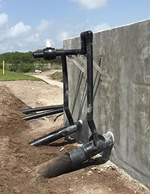
Consider an effective gas pressure removal system in the sump by installing vertical pipes on the riser pipes behind structures, on top of the perimeter berm, shown here. The vertical pipes are blind-flanged initially at cell construction completion. If the gas pressure build-up becomes significant, or odors are detected in the sump area, the landfill operator connects the vertical pipes to a vacuum source near the sump.
Using a connecting pipe to a vacuum source can also be used to discharge condensate from the gas collection and control system directly into the leachate collection riser pipe.
For a double lining system, with a riser pipe in the primary system and another in the secondary system, both risers will have vertical pipes on them, and both connected to the vacuum source.
However, condensate flowing down the connecting pipe from higher elevations toward the risers should not enter the secondary system. Block it by using a manifold, as shown in the image.
Operators may have a vertical pipe installed on the leachate collection pipe cleanout to apply vacuum directly to the leachate collection pipe.
Keeping gas pressure low in and around the leachate collection pipe promotes the free flow of leachate through the geocomposite or granular medium drainage layer to the leachate collection pipe, and improves leachate removal from the disposal cell.
Using gas removal piping at leachate sumps is highly recommended for warm or elevated temperature landfills where efficient leachate removal from the leachate collection system is another means for controlling landfill temperatures.
About the Author: Ali Khatami, Ph.D., PE, LEP, CGC, is a Project Director and a Vice President of SCS Engineers. He is also our National Expert for Landfill Design and Construction Quality Assurance. He has nearly 40 years of research and professional experience in mechanical, structural, and civil engineering.
Learn more at Landfill Engineering and Leachate Management
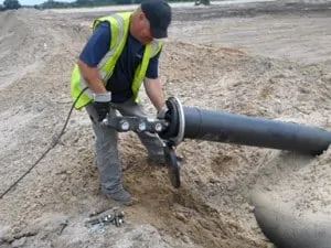
Survivability of leachate collection pipes depends upon the gravel placed on all sides of the pipe. Proper placement of gravel around the pipe and the granular soil material over the completed pipe/gravel/geotextile burrito is of significant importance in the protection of the leachate collection pipe.
Read the article by Dr. Ali Khatami here.
SCS Advice from the Field is a collection of blogs, articles, and white papers written by SCS professionals like Dr. Khatami. Search “advice from the field” to browse all of the topics.

The drainage layers of landfill final covers normally go through a rigorous flow capacity evaluation. This evaluation is necessary to ensure that the volume of water reaching the drainage layer due to percolation of precipitation water through the final cover upper soil layer will not overwhelm the drainage layer in its flow path. If the flow volume in the geocomposite drainage layer is greater than the capacity of the drainage layer, water will exit the geocomposite and enter the overlying soil. The water entering the soil layer can easily saturate the lower portion of the soil layer, which will affect the stability of the slope. The geocomposite should always be designed to have a flow capacity greater than the flow rate of water running through it.
Concave areas of a landfill slope experience flow patterns quite different from slopes that go straight down. Slopes with concaved geometry have an unequal crest and toe lines – the toe line being smaller than the crest line. As a result, the width of the concaved slope decreases as the distance from the crest line increases in the downward direction. The narrowest width of the concaved slope is at the toe of the slope. The drainage layer on the slope experiences the same width change from the crest line to the toe line. This means that the overall width of the channels that carry water within the geocomposite drainage layer decreases toward the toe line, and, therefore, the depth of water in the channels increases. This phenomenon is referred to as flow convergence, and the convergence is toward the vertical centerline of the concaved slope. The flow convergence may be significant enough to increase the water depth in the geocomposite in the vicinity of the vertical centerline of the slope to greater than the thickness of the geocomposite. That, in turn, forces water out of the geocomposite and into the overlying soil, which may result in slope stability problems.
To complement the geocomposite flow capacity along the vertical centerline of the concaved slope in order to accommodate the higher water flow rates in the system, a pipe-gravel-geotextile (a burrito) may be constructed along the vertical centerline of the slope. The burrito, which would be positioned directly over the geocomposite drainage layer, increases the flow capacity of the system at and in the vicinity of the vertical centerline of the concaved slope. The burrito will receive water from the geocomposite where the water depth exceeds the geocomposite thickness. The burrito will be connected to the toe drain system at the toe of the slope, and water in the burrito will be discharged to the toe drain. The water in the toe drain, in turn, leaves the final cover through lateral drain pipes at regular intervals.
It should be noted that not every concaved slope requires a burrito. Some concaved slopes may be fairly wide, and the convergence of water inside the geocomposite may not be significant enough to cause the depth of water to exceed the geocomposite thickness. But, if the concavity of the slope is significant, a severe convergence of water in the geocomposite drainage layer is more likely. In that case, a burrito along the vertical centerline of the concaved slope is highly recommended.
A cautionary construction related note seems to be appropriate at this point. During construction, extra care should be taken to ensure that all geocomposite panels within the boundary of the concaved slope run such that the machine direction of the panels follows a path from the top toward the bottom of the slope. If some geocomposite panels are installed with the machine direction running across the slope width, significant turbulence in the flow will be created at the point where panels running in one direction transition to the panels running in the other direction. The turbulence will reduce the flow capacity of the geocomposite.
If you are planning to install a final cover over a portion of the slope that has concaved geometry and you want your final cover design to properly address flow volumes in the geocomposite drainage layer, please contact us. SCS Engineers has extensive experience with these types of circumstances, and we will gladly review your case and make recommendations. Learn more here.
If you have comments or questions about this article, please contact Dr. Ali Khatami.
Ali Khatami, Ph.D., PE, LEP, CGC, is a Project Director and a Vice President of SCS Engineers. He is also our National Expert for Landfill Design and Construction Quality Assurance. He has nearly 40 years of research and professional experience in mechanical, structural, and civil engineering.
Dr. Khatami has acquired extensive experience and knowledge in the areas of geology, hydrogeology, hydrology, hydraulics, construction methods, material science, construction quality assurance (CQA), and stability of earth systems. Dr. Khatami has applied this experience in the siting of numerous landfills and the remediation of hazardous waste contaminated sites.
Dr. Khatami has been involved in the design and permitting of civil and environmental projects such as surface water management systems, drainage structures, municipal solid waste landfills, hazardous solid waste landfills, low-level radioactive waste landfills, leachate and wastewater conveyance and treatment systems. He is also involved in the design of gas management systems, hazardous waste impoundments, storage tank systems, waste tire processing facilities, composting facilities, material recovery facilities, landfill gas collection and disposal systems, leachate evaporator systems, and liquid impoundment floating covers.
By Ali Khatami, Ph.D, P.E., SCS Engineers National Expert
Leachate seeping out of a landfill slope can be a major issue during the active life of a landfill, and waste operators undertake significant efforts to control and manage it. Uncontrolled seeps can cause soil erosion on the slope, odor issues, and unpleasant scenery on the landfill slope which is visible to adjacent public roads or properties. Leachate can also travel beyond the liner boundaries into perimeter ditches.
Leachate also can seep below the final cover, and that causes a different set of problems. Leachate seeps below final landfill covers are rarely discussed because of the general consensus that they become inactive after construction of the final cover system. That may be true under certain conditions, but very often, leachate seeps remain active as long as the source of water remains active and continues discharging through the seep locations. Leachate seeps below final covers can potentially:
If the final cover geomembrane is not welded to the bottom liner geomembrane, leachate seeping to the toe of the slope can reach the landfill perimeter ditch and contaminate the surface water, or it can percolate into the ground and cause ground water contamination that may be detected in nearby groundwater monitoring wells. Leachate seep also may enter the perimeter berm structure and saturate the berm to the point that the stability of the landfill slope becomes a concern.
If the final cover geomembrane is welded to the bottom liner geomembrane, the only way to address the accumulation of leachate under the cover at the toe of the slope is to open the geomembrane, remove the leachate, and close the geomembrane again. However, this process does not solve the seep problem, which will continue to recur.
SCS has designed various leachate toe drain systems to collect and dispose of leachate that flows below the final cover geomembrane. Leachate toe drains have become a standard feature in the final cover designs for some of our clients who have experienced the benefits of the system.
If you have leachate seep issues at your landfill, please contact SCS. We can develop a design specific to your landfill and the conditions at your facility. We also provide construction recommendations and a preliminary cost estimate for implementation of the system. SCS has extensive experience with the permitting of these systems; we prepare modification applications for permitting purposes and obtain approval from the state regulatory agency. SCS can also prepare the construction plans. We also offer design-build options, employing our SCS Field Services Construction group to construct the system, which often can be a cost-effective way to implement your system.
 Questions? Contact Ali Khatami, PhD, PE, LEP, CGC, is a Project Director and a Vice President of SCS Engineers. He is also our National Expert for Landfill Design and Construction Quality Assurance. He has nearly 40 years of research and professional experience in mechanical, structural, and civil engineering. Dr. Khatami has acquired extensive experience and knowledge in the areas of geology, hydrogeology, hydrology, hydraulics, construction methods, material science, construction quality assurance (CQA), and stability of earth systems. Dr. Khatami has applied this experience in the siting of numerous landfills and the remediation of hazardous waste contaminated sites.
The benefits of implementing these cleaning recommendations for leachate collection pipes will help keep the pipes clean and fully functioning; helping landfill operators prevent the potentially serious complications of clogged pipes and immovable leachate.
By Dr. Ali Khatami, P.E., SCS Engineers
Some states require that leachate collection pipes be cleaned with high-pressure jets on a regular basis (for example, every ten years or even more frequently); however, the rules don’t clarify or set forth the specific conditions under which the jet cleaning should be performed. Some landfills have undertaken jet cleaning while the pipes are partially or fully submerged in leachate above the liner. Unfortunately, jetting under water may drastically reduce the effectiveness of the pressurized jet, resulting in a pipe that is not cleaned properly. This is even more important when the jetting is intended to remove biological growth on the pipe walls and in the perforation openings.
In addition, many states do not require videotaping the pipe after jetting. Videotaping is the best way to verify that the pipe was cleaned successfully. If the leachate collection pipes are not properly cleaned, then over a period of 20 years or so, they can be adversely impacted by severe biological growth and buildup in the pipe perforations to the point that liquid can no longer enter the pipe.
Another shortcoming is that the rules do not specifically require that the riser pipes (where the submersible pumps are located) be cleaned or videotaped. Therefore, due to the added costs, some landfill operators may not clean the riser pipes as part of the required cleaning events, or they may delay such cleanings for an extended period. This can prevent leachate from flowing into the riser with the direct and serious consequence that leachate cannot be removed from the sump.
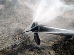
Another issue to consider is that pressurized jet cleaning procedures do not necessarily push the solids that separate from the pipe wall out of the pipe inlet opening through which the cleaning nozzle entered the pipe. As a result, these solids flow out of the pipe and into the gravel bedding on the outside of the pipe, and can potentially clog the void within the gravel pack around the pipe or in the sump. Clogging the sump gravel can mean reduced flow capacity from the leachate collection pipe to the riser pipe and the submersible pumps.
To resolve these issues, SCS recommends the following:
The benefits of implementing these recommendations will help keep the pipes clean and fully functioning. These suggestions help prevent potentially serious complications that the landfill operator may have to address if the pipes are clogged and leachate cannot be removed.
Questions? Contact Ali Khatami, PhD, PE, LEP, CGC, is a Project Director and a Vice President of SCS Engineers. He is also our National Expert for Landfill Design and Construction Quality Assurance. He has nearly 40 years of research and professional experience in mechanical, structural, and civil engineering. Dr. Khatami has acquired extensive experience and knowledge in the areas of geology, hydrogeology, hydrology, hydraulics, construction methods, material science, construction quality assurance (CQA), and stability of earth systems. Dr. Khatami has applied this experience in the siting of numerous landfills and the remediation of hazardous waste contaminated sites.
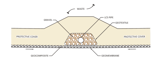
One general problem that is encountered in traditional designs is the potential for clogging of geotextiles in the vicinity of the leachate collection pipes.
Traditionally, leachate collection pipes are encased in gravel, wrapped in geotextile, and positioned above the leachate collection system geocomposite drainage layer inside a trench or at the trough of the bottom of a cell. In a traditional design, leachate travels through the geonet component of the geocomposite and reaches the leachate trench where the leachate collection pipe is located. Here, leachate must flow out of the geocomposite, through the upper geotextile component, and then through the geotextile wrapped around the gravel, before entering the gravel and eventually flowing through the pipe. The flow through the geotextiles is concentrated in small areas on the two sides of the leachate collection pipe-gravel-geotextile wrap. Considering the large volume of leachate that follows this path over the life of the cell, it is evident why traditional designs are doomed to clog.
The clogging impedes the free flow of leachate from the geocomposite drainage layer to the leachate collection pipe. As the clogging occurs, the leachate must find a new flow path (most likely further back from the collection pipe), and flow out of the geocomposite, through the geotextile wrap at a different location, and eventually enter the gravel and pipe. This new location will eventually clog as well for the same reasons that the initial location was clogged. This process continues until the geotextile within the leachate trench becomes completely clogged and the system loses functionality. Unfortunately, the periodic cleaning of leachate collection pipes (usually every few years) cannot address this issue because the problem is outside the pipe and the high-pressure jets inside the pipes do not reach the clogged locations.
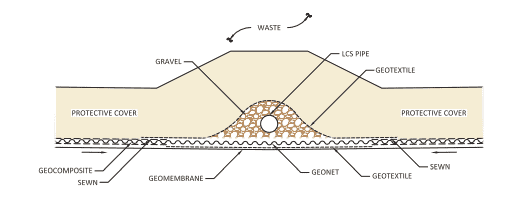
The solution is to eliminate geotextiles from the flow path of the leachate, extending from the geocomposite drainage layer to the leachate collection pipe. Over the past several years, SCS has successfully designed and constructed numerous landfill cells with no geotextile in the flow path of leachate from the geocomposite drainage layer to the leachate collection pipe. The design follows the “Rule of Transmissivities” which dictates that a proper design should provide the free flow of leachate from one medium to another and that only occurs when the transmissivity of the latter medium is equal to or greater than the transmissivity of the former medium. If a design does not satisfy the Rule of Transmissivities, there may be potential for clogging, bottlenecking of flow, and other consequences resulting from impeded flow in the system.
SCS Engineers is a leader in the design of landfill lining systems, and we have experience with issues that may not be familiar to other firms. If you are interested in the design of a leachate collection system at your facility, please contact SCS. Our professional engineers will gladly review your design and make recommendations if needed. We can identify potential issues and improve designs to prevent future problems and maintenance during the life of your facility.
Questions? Contact Ali Khatami, PhD, PE, LEP, CGC, is a Project Director and a Vice President of SCS Engineers. He is also our National Expert for Landfill Design and Construction Quality Assurance. He has nearly 40 years of research and professional experience in mechanical, structural, and civil engineering. Dr. Khatami has acquired extensive experience and knowledge in the areas of geology, hydrogeology, hydrology, hydraulics, construction methods, material science, construction quality assurance (CQA), and stability of earth systems. Dr. Khatami has applied this experience in the siting of numerous landfills and the remediation of hazardous waste contaminated sites.
Read more here. Rule of Transmissivities at Material Interfaces in Landfill Leachate Collection Systems, in Talking Trash
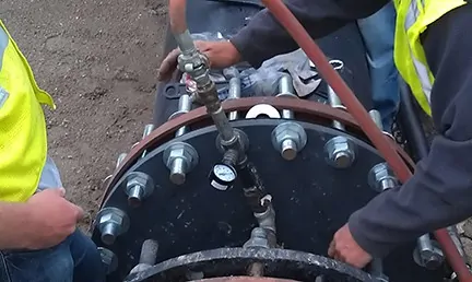
Pressure testing of HDPE pipes takes place at almost every landfill lining system and landfill gas collection system construction project. The pipes must be tested to make sure the fusion welds are intact and are not leaking. When engineers specify pressure testing, they identify the required test pressure, the duration of the test, and the allowable pressure drop at the completion of the test. The test pressure may vary from one pipe application to another. For example, the specified test pressure may be as high as 1.5 to 2 times the maximum service pressure in the pipe for leachate forcemain pipes; whereas for pipes used in landfill gas collection systems, where the pipes are under vacuum, the specified test pressure may be less. Test duration may vary from one hour to a few hours, and the allowable pressure drop may vary from zero to a percentage of the initial pressure.
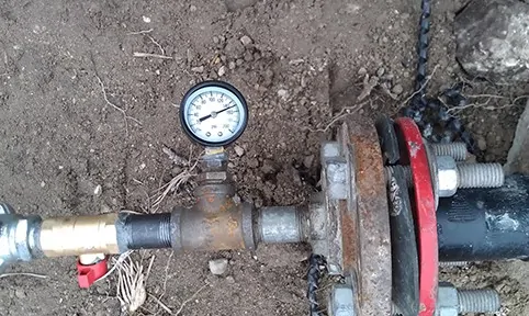
What is often missing from pressure test specifications is the effect of the ambient temperature variation on the pressure changes within the pipe during the test. If incompressible fluid (e.g., water) is used for pressure testing, pressure changes due to ambient temperature variations are less significant than when compressible fluid (e.g., air) is used.
For incompressible fluids, SCS has developed a mathematical model that enables the engineer or contractor to calculate pressure changes due to ambient temperature variations during the test. The calculated pressure change should be considered when evaluating whether the test results are passing or failing. Increasing ambient temperatures during the test may cause expansion in the pipe, and the expansion causes an additional pressure drop that is not caused by any leak in the welds. On the other hand, decreasing ambient temperatures may cause contraction in the pipe, which increases pressure in the pipe. In this case, a pressure drop due a leak in the weld may not be detected because of a higher pressure created inside the pipe due to pipe contraction. It is recommended that engineers or contractors use the mathematical model to calculate a modified allowable pressure drop by considering the calculated pressure change (positive for pipe expansion or negative for pipe contraction) before the pass/fail assessment is carried out.
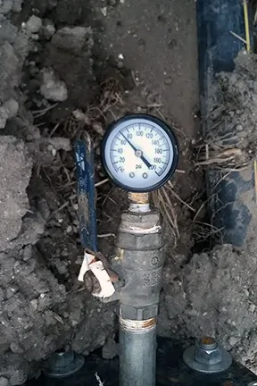
Recently during the test period in the field, a pressure drop was experienced that slightly exceeded the specified allowable pressure drop. Field staff reported ambient temperature variation during the two-hour test. When the modified allowable pressure drop was calculated using SCS’s model to account for the ambient temperature variation, the test ended up passing. Note that field documentation is extremely important for assessing the pass/fail results. This becomes even more important when the specified test duration is several hours long and the ambient temperature variation is significant.
Questions? Contact Ali Khatami, PhD, PE, LEP, CGC, is a Project Director and a Vice President of SCS Engineers. He is also our National Expert for Landfill Design and Construction Quality Assurance. He has nearly 40 years of research and professional experience in mechanical, structural, and civil engineering. Dr. Khatami has acquired extensive experience and knowledge in the areas of geology, hydrogeology, hydrology, hydraulics, construction methods, material science, construction quality assurance (CQA), and stability of earth systems. Dr. Khatami has applied this experience in the siting of numerous landfills and the remediation of hazardous waste contaminated sites.
Read more here. Pass/Fail Criterion for HDPE Pipe Pressure Testing Using Incompressible Fluid, in Talking Trash, March 2015
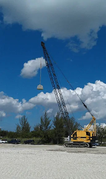
Dynamic compaction is a construction technique that increases the density of soil/waste deposits by dropping a heavy weight at regular intervals to consolidate and improve the geotechnical characteristics of the deposit so that it can be suitable for redevelopment. This construction technique can be used to transform otherwise undevelopable property, such as old landfill areas, into developable property.
Most soil types can be improved by dynamic compaction; the method is particularly well suited to non-organic, irregular fill, where variable characteristics such as solid wastes are present. Field conditions and several other parameters are considered when designing and implementing dynamic compaction programs to keep costs in line. The primary considerations include, but are not limited to, waste delineation, distance from the ground surface to ground water, waste thickness, minimum energy, and selection of dynamic compaction parameters.
The following factors and associated costs should be evaluated if dynamic compaction is to be considered:
Major change orders and environmental impacts can be expected if the plan does not address these factors.
If you decide to consider dynamic compaction in your redevelopment project, having onsite construction quality assurance monitoring during the process is important. CQA monitoring will verify that the work is implemented as designed and permitted, and that proper techniques are used to make sure the proper distribution of energy into the ground is taking place. The CQA monitor will also check to see that the final configuration of the fill is achieved, a safe working environment is maintained., and that ground vibrations are monitored near adjacent structures to to prevent structural damage.
For developments involving construction of buildings over a dynamically compacted areas, a combustible gas barrier layer is generally required below the building footprint to safely collect and vent subsurface combustible gases (i.e., typically methane) to the environment. Construction costs associated with a combustible gas barrier layer should include the following:
In summary, dynamic compaction is a proven geotechnical construction engineering method that can be used to improve certain landfill areas to support redevelopment. SCS Engineers has completed many projects of this nature and is ready to serve and help to bring your project in service.
Related Article
Pursuing Dynamic Compaction, by Ali Khatami, Ph.D., Bruce Clark, P.E., and Myles Clewner, L.E.P., Waste Age
Sample Case Studies
Environmental Due Diligence – Procacci Site, Sweetwater, Florida
Landfill Engineering and Consulting – Medley Landfill, Miami-Dade County, Florida
Landfill Site Redevelopment for the City of Industry, California
Ali Khatami, PhD, PE, LEP, CGC, is a Project Director and a Vice President of SCS Engineers. He is also our National Expert for Landfill Design and Construction Quality Assurance. He has nearly 40 years of research and professional experience in mechanical, structural, and civil engineering.
Dr. Khatami has acquired extensive experience and knowledge in the areas of geology, hydrogeology, hydrology, hydraulics, construction methods, material science, construction quality assurance (CQA), and stability of earth systems. Dr. Khatami has applied this experience in the siting of numerous landfills and the remediation of hazardous waste contaminated sites.
Dr. Khatami has been involved in the design and permitting of civil/environmental projects such as surface water management systems, drainage structures, municipal solid waste landfills, hazardous solid waste landfills, low-level radioactive waste landfills, leachate and wastewater conveyance and treatment systems. He has also been involved with the design of gas management systems, hazardous waste impoundments, storage tank systems, waste tire processing facilities, composting facilities, material recovery facilities, landfill gas collection and disposal systems, leachate evaporator systems, and liquid impoundment floating covers.
Corporate Headquarters