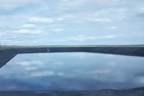
Evaporation ponds are one of the most cost-effective ways of disposing of leachate after separating the oil. Black geomembrane liners also help to enhance evaporation.
Managing oil and gas waste is challenging, even when practicing due diligence. The job requires impeccable skill and attention and sometimes outside support, which Colorado operators recently learned when they found high oil content in leachate coming out of their sump. They turned to SCS, knowing through their longstanding relationship with the engineers and that their liquids management team could deal with oil-laden wastewater.
Ensuring sustainable outcomes begins with collecting and analyzing comprehensive data that become the building blocks for a feasibility study. The study helps with immediate challenges and builds a more holistic approach to tackle increasingly expensive operation challenges at landfills.
“First, we talk about the site’s leachate history, including quality and quantity. What is the source of the waste generating the leachate, and where is it deposited? How are liquids used in current operations? The current practice used the liquids on the landfill surface for dust control, leaving an unsightly oily sheen.
Once we talk about how the site currently manages these liquids, we discuss options for future handling for improvement,” says Neil Nowak, SCS Engineers project director. “You’ve got to have a holistic understanding of day-to-day operations with the data to solve the problem cost-effectively.”
Neil’s preliminary research led to one recommendation to meet all the criteria – separate oil and water from leachate as the liquid exits the pump. The separation process can reduce the oil-laden leachate volume by 70 percent.
The technology works by separating the leachate into oil and water portions using an oil/water separator, such as a gun barrel tank, which is low cost and effective. After piping the water to an evaporation pond, the collected oil is sent offsite for future handling, usually disposal.
“This method gives the operator a better option for dealing with the leachate over the current practice of spraying it on the landfill surface for dust control,” Nowak says.
Spraying usually provides an alternative for liquids while reducing disposal time and cost. However, he explains, oil-laden leachate is a different beast than typical MSW liquids and calls for a more creative solution to remain within regulatory compliance.
Oil and water separation eliminates the aesthetics issues at the site with its previous practice. The greater value is that this method gives operators full control of oil’s movement, which can otherwise be very hard to accomplish.
“Oily leachate can adhere to the wheels of equipment that move dirt over the landfill surface; consequently, it ends up in places operators do not want it to go. Oil and water separation technology is a reliable way to keep it out of surface drainage areas and ensure it does not infiltrate into groundwater outside of the lined space,” Nowak explains.
Operators avoid short- and long-term consequences springing from compliance issues, but beyond today, the technology that SCS sizes operates for 20-plus years and helps prepare them for the long haul.
This option enables waste pros who take on growing demand from the oil and gas industry to protect the environment and public health, even as volumes increase. Oily liquids are particularly challenging for wastewater plants. Separation technology provides greater assurance that the landfill will still have a home for their leachate as wastewater treatment plants raise the bar on what they will allow.
The remaining question…
What is the most cost-effective and safe way to eliminate the filtered oil?
The solution for the immediate need is straightforward and simple. Depending on geology, local regulatory policy, and cost factors, solidification or injection are the most common, safe practices now, but reuse options are under development. Reuse and prevention are part of a longer-term landfill strategy, so Neil draws on his colleagues’ expertise.
Nowak’s expertise comes from years of experience supporting the oil and gas industry. Backing him is national liquid management expert Nathan Hamm, who lends technical expertise and insight on best practices for reducing leachate.
Explains Hamm:
Commonly the best bang for your leachate management dollar is to reduce the volume of leachate or wastewater to treat in the first place. Operators can begin by diverting stormwater away from active portions of the landfill, then installing a better cover system. Depending on the landfill’s need and location, reducing the size of new cells and timing those new cells to come online during low precipitation seasons is practical. Leachate minimization practices such as these directly reduce the treatment system capital and ongoing operational costs.
The Colorado operator now has oil and gas waste management options and has a comprehensive, site-specific review of leachate management with a clear understanding of where there is room for improvement.
As far as their immediate priorities, says Nowak, “We have left them with enough thought-out information to make informed decisions, and for now, they are leaning toward the oil and water separation technology. Though they can keep operating without it, they are looking to get ahead of possible compliance issues by making changes voluntarily, which are usually less costly in the end and demonstrates social responsibility to the Colorado Department of Public Health and Environment and the EPA.
Higher operating costs can translate to higher tipping fees for consumers; onsite leachate management treatment may be the most cost-effective compliance solution.
Lately, landfill operators are putting stock in onsite landfill leachate treatment systems as a strategy to stay on top of increasing requirements in their already demanding regulatory world. Leachate treatment systems help meet tightening restrictions on liquids that landfills send to municipal wastewater treatment plants or discharge directly. And onsite leachate treatment gives operators a leg up should they one day have to deal with any emerging contaminants found on an expanding list.
With their eyes on compliance, landfill owners and operators are looking to leachate treatment systems that can ease the impact of soaring leachate disposal costs. Of course, the more contamination, the harder the hit since higher contaminants can mean higher municipal treatment plant surcharges or the landfill having to haul its leachate longer distances to a treatment plant that will accept it. Both examples usually result in higher treatment, disposal, and hauling costs.
A spike in its ammonia concentrations was enough impetus for one Oregon landfill operator to turn to SCS Engineers a few months ago. At its highest levels, the ammonia climbed to 50-fold what many small wastewater treatment plants, like the one in the Northwest, will take over the long-term.
Project Director Shane Latimer and Technical Lead Sam Cooke got on the stick to figure out how their client could keep hauling and disposing of leachate at the local wastewater treatment plant it has routinely relied on for years.
Coming up with a plan is a complex, multi-step process that requires looking through many lenses. To design a cost-effective, efficient treatment facility, Latimer and Cooke use an in-house multidisciplinary team of co-workers from Project Management, Chemical Engineering, Civil Engineering, and Geotechnical Engineering. The team performs in-depth analyses to identify the most economical and feasible technology. A design that in this case not only addresses ammonia but prepares the operator for emerging contaminants, such as the possible need for per and polyfluoroalkyl substances (PFAS) reduction, which Cooke describes as a train that has not yet arrived in Oregon but has left the station and is heading down the track.
Starting with the most immediate concern, Cooke says, “Our client had seen ammonia concentrations between 500 and 1,500 mg per liter, which is high. Acceptable ammonia levels can vary depending on the type of facility and how much leachate they expect to get compared to their total flow. But small treatment plants like the one our client depends on will set ammonia limits of about 25 or 30 mg per liter,” he says.
SCS begins with a leachate pretreatment options analysis to dive into details beyond ammonia levels – spikes in ammonia call for close attention. Still, there’s more to consider in masterminding a robust and fitting plan to manage the complex process.
“These are biological treatment systems, and there is no one-size-fits-all answer. You need to know how these systems will react to whatever is in your leachate, so you have to account for more than ammonia, or whatever your constituents of concern are,” Latimer says.
SCS’s leachate contaminant analyses use the landfill’s historical data along with what they learn from tests that SCS orders to understand alkalinity, pH, and carbon, among other leachate chemistry puzzle pieces.
“We look at concentrations of raw leachate, flow rate, pretreatment requirements, and other factors. We want to get a comprehensive picture of the problem and ultimately make the best treatment decision to get compound concentrations down to acceptable discharge levels,” Latimer explains.
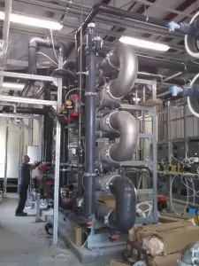
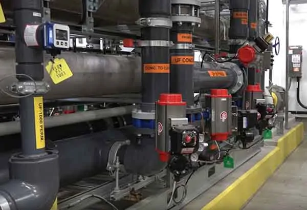
What customized solution did the team design for the client in Oregon? The system of choice is a membrane bioreactor (MBR), which combines membrane separation technology with traditional activated sludge technology with optional reverse osmosis treatment. The design is a compact, efficient, biological wastewater treatment plant.
Pictured is a similar Reverse Osmosis System. NCDEQ’s lab-certified results from sampling show that the landfill’s RO system effectively filters out all 33 PFAS contaminants before discharging treated water into the Northeast Cape Fear River.
“An MBR is an elegant solution. We found it to be a good choice for this application for several reasons. It takes up relatively little space and fits well within the available plant footprint. It produces a relatively low-volume waste sludge stream. And it can cost-effectively treat multiple constituents of concern, so should new leachate chemistry issues arise, an MBR can address many of them,” Cooke says.
Being able to handle multiple concerns if and when they arise is key here. Cooke and Latimer wanted not only to get the immediate problem in check but see that the client has a dynamic and robust system to tackle whatever new challenges may be down the road.
When SCS goes into design mode, they plan ahead by engineering modular systems to add additional treatment methods if and when they’re necessary.
“For instance, MBR treats the leachate to reduce ammonia, other nutrients, organics, and suspended solids. By leveraging this treatment method first, you eliminate a lot of the bulkier constituents. But we left room for a modular addition such as reverse osmosis for “polishing,” treating MBR discharge for other minor constituents including PFAS,” Cooke says.
The client who came to SCS for a relatively inexpensive remedy for an ammonia problem now has a feasible, economical asset for leachate management.
“These investments are good security for landfill operators,” says Latimer. “If a municipal wastewater treatment plant is struggling to meet its standards, eliminating one contributing source of wastewater, like a landfill, could potentially solve several issues, such as ammonia, biochemical oxygen demand, and total suspended solids.”
But these treatment systems provide added security for more than the landfill.
“When disposal sites invest in sound leachate treatment systems, it’s also good for municipal wastewater treatment plants. It assures them that landfill operators will help them with the overall regulatory burden. We are helping them both to prepare for present and future challenges,” says Latimer.
FOG are the fats, oils, and grease substances, primarily from food processing and manufacturing, requiring wastewater treatment.
Not long ago, a Utah food manufacturer turned to SCS with a persistent problem: high concentrations of fats, oils, and grease (FOG) in its wastewater— high enough to clog the city’s sewer line, knock it out of compliance, and cost it a steep surcharge year after year. As the plant worked toward a solution, its customers’ demand was growing; it reached a point where it had to expand to keep up, and that’s when the quandary came to a head. The meat processor couldn’t get a permit for expansion until the FOG was in check.
Within 18 months, SCS Project Director Mark Pearson and his team of liquid management gurus had their client within acceptable discharge limits for the first time in years. Actually, the plant’s doing a lot better than meeting the city’s requirements. Its FOG concentrations, which had spiked to thousands of mg/L, are consistently down below the established discharge limit of 200 mg/L.
The scenario Pearson walked into is that the wastewater generation and pollutant loading were highly variable as flows fluctuated. Due to hydraulic limitations, the treatment system couldn’t keep up with volumes during peak flows. As a result, the influent (untreated wastewater) was discharged from the plant to the sewer to the municipal wastewater treatment plant. And because the system was overtaxed, it did not sufficiently break down the FOG, which exacerbated the problem, wreaking havoc with the city’s collection pipes.
After completing the initial assessment, Pearson’s team developed a multifaceted approach to debottleneck the system’s hydraulics and make other improvements to increase FOG removal efficiency.
Pearson; Dean Free, senior project manager; and Nathan Hamm, program lead for wastewater and liquids management, came up with a design that achieves two main goals: It eliminates uncontrolled discharge from the plant; it greatly reduces concentrations of FOG—cutting the contaminant load to the city. Not only is the client within discharge limits, but it’s also pushed through its most immediate barrier to expansion permit approval. And it’s improved its relationship with the city.
The solution is a complex one involving chemistry, mechanical engineering, and electrical engineering. But to pare a lot of fine details down to the nitty-gritty, Pearson says:
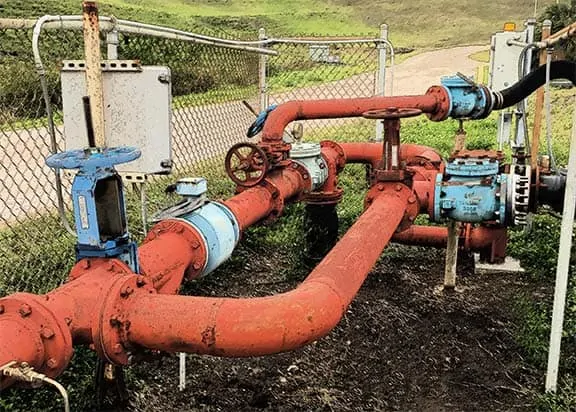
“We put in screens that remove solids in the wastewater. We constructed a 60,000-gallon tank to equalize the flow coming to the plant. We adjusted pH to help optimize the wastewater treatment chemicals’ effectiveness. We separated the influent tank from the effluent (treated water) pipes to solve a problem where the influent would overflow into the effluent through a perforated wall. The new piping setup makes overflow impossible. And to further fortify the system, we installed a lift station to capture previously untreated wastewater.”
As a bonus, the team installed a tank that the separated FOG residual is pumped to, then hauled to a compost facility for beneficial use.
Besides adding these system enhancements, the SCS team took capabilities further with a process control and instrumentation component. The technology monitors flow rates, temperatures, tank levels, and other conditions. It processes the data and automatically makes adjustments to achieve treatment goals, avoid production downtime, and enable operators to respond proactively should they see a red flag.
Comparing the old to the new way of monitoring and analyzing, Pearson says, “What our client had before was rudimentary information. And while they could monitor conditions, they had to walk around the plant. All of the operational data can be viewed on a screen now from one location. They have more data at their fingertips and more capability to make adjustments to avoid discharge exceedances.”
The wastewater treatment system upgrade was done as a design-build to speed the timeframe while also increasing efficiency. “We could immediately start rather than put it out to bid. We could do construction as we designed. And there was one entity and one point of responsibility. So what’s cool is we leverage both SCS engineering and construction capabilities to solve problems,” Hamm says.
He and his colleagues have the know-how to pivot on a dime if they have to, and there were a couple of times it was necessary, including when the client brought new management on board midway through the installation process. The new team preferred different instrumentation and had a specific scheme in mind.
“We were in the process of installing the original instruments. But we were able to incorporate their equipment preference midstream. We had to figure out how to get new instruments installed and ensure they were perfectly integrated with the computer control system that takes readings from the instruments. It was what they wanted, so we saw that they got it,” Pearson says.
While he and his co-workers’ jobs as project design and build engineers are done, they have not faded from the picture. They provide ongoing technical support when the client needs assistance with troubleshooting. The automated control system has helped.
“This is a robust and complex mechanical treatment system. If by chance, something was wrong, our client can transmit data that comes out of the process controller so we can work remotely to determine if process changes are needed. If they are, we can often make those changes from offsite, and quickly,” Hamm says.
But the SCS team also plans so that its client is equipped to ensure its success moving forward. They provide operator training. And they developed a standard operating and maintenance procedures manual and a checklist to track data and activities transferred from shift to shift, providing operators a standard and seamless way to communicate.
The busy Utah plant is on a good trajectory, with solid footing.
Says Pearson: “Before, they could not expand the plant or even continue their operations much longer if they did not get the FOG under control. Now they can operate continuously, discharge to the city, and they have potential to expand their plant because they are showing the regulators they can stay within their permit limits.”
Complementing the Interstate Technology and Regulatory Council’s – ITRC, PFAS Technical and Regulatory Guidance, the website now has ITRC Per- and Polyfluoroalkyl Substances – PFAS, and Risk Communication Fact Sheets available. The site and updated content replace older fact sheets with more detailed information and useful for those who wish to understand the discovery and manufacturing of PFAS, information about emerging health and environmental concerns, and PFAS releases to the environment with naming conventions and federal and state regulatory programs.
SCS Engineers’ professionals recommend further reading to understand specific chemicals or subgroups of chemicals under study to comprehend PFAA behavior in the environment. There are appropriate tools to develop a site-specific sampling and analysis program and considerations for site characterizations following a PFAS release.
Firefighting Foams – Aqueous film-forming foam (AFFF) users and those who manage AFFF releases.
The Interstate Technology and Regulatory Council (ITRC) is a state-led coalition working to reduce barriers to the use of innovative air, water, waste, and remediation environmental technologies and processes. ITRC documents and training can support quality regulatory decision making while protecting human health and the environment. ITRC has public and private sector members from all 50 states and the District of Columbia and is a program of the Environmental Research Institute of the States (ERIS), a 501(c)(3) organization incorporated in the District of Columbia and managed by the Environmental Council of the States (ECOS).
ITRC Goals
National paradigm shifts for using new technology
Harmonized approaches to using innovative technology across the nation
Increased regulatory consistency for similar cleanup problems in different states
SCS Engineers
Reduce the review and permitting times for innovative and proven approaches to environmental prevention and mitigation programs
provides Prevention with Risk Management, Process Safety, and Spill Prevention Plans
Can help reduce the possible impact on environmental insurance
Faster cleanup with less environmental impacts
Decrease compliance costs
Provides technical and regulatory expertise for public outreach
Regularly engages with state and federal regulators and compliance enforcement as a trusted engineering firm.
The industry is designing and building more substantive drainage features and larger collection systems from the bottom up, that maintain their integrity and increase performance over time, thus avoiding more costly problems in the future.
Waste360 spoke with three environmental engineers about what landfill operators should know about liquids’ behavior and what emerging design concepts help facilitate flow and circumvent problems such as elevated temperature landfills, seeps, and keep gas flowing.
The engineers cover adopting best practices and emerging design concepts to facilitate flow. They cover topics such as directing flow vertically to facilitate movement to the bottom of the landfill, drainage material, slope to the sump percentages, vertical stone columns, installing these systems at the bottom before cells are constructed, and increasing cell height to prevent the formation of perched zones.
Ali Khatami, one of the engineers interviewed, has developed standards for building tiered vertical gas wells that extend from the bottom all the way up. He frequently blogs about landfill design strategies that his clients are using with success. His blog is called SCS Advice from the Field. Dr. Khatami developed the concept of leachate toe drain systems to address problems tied to seeps below the final cover geomembrane. These seeps ultimately occur in one of two scenarios, each depending on how the cover is secured.
Landfill Gas Header: Location and BenefitsBy continuing to design gas header construction on landfill slopes, all of the components end up on the landfill slope as well. You can imagine what type of complications the landfill operator will face since all of these components are in areas vulnerable to erosion, settlement, future filling, or future construction. Additionally, any maintenance requiring digging and re-piping necessitates placing equipment on the landfill slope and disturbing the landfill slope surface for an extended period.
AIRSPACE, the Landfill Operators’ Golden EggAirspace is a golden egg, the equivalent to cash that a waste operating company will have overtime in its account. With each ton or cubic yard of waste received at the landfill, the non-monetary asset of airspace converts positively to the bottom line of the …
Gas Removal from Leachate Collection Pipe and Leachate SumpKeeping gas pressure low in and around the leachate collection pipe promotes the free flow of leachate through the geocomposite or granular medium drainage layer to the leachate collection pipe and improves leachate removal from the disposal cell. Using gas removal piping at leachate sumps is highly recommended for warm or elevated temperature landfills where efficient leachate removal from the leachate collection system is another means for controlling landfill temperatures.
Leachate Force Main Casing Pipe and Monitoring for LeaksLandfill operators may add a casing pipe to their leachate force main for additional environmental protection. Consequently, the leachate force main is entirely located inside a casing pipe where the leachate force main is below ground. In the event of a leak from the leachate force main, liquids stay inside the casing pipe preventing leakage …
Pressure Release System Near Bottom of LandfillsPressure Release System Near Bottom of Landfills – Essential Component for Proper Functioning of the Landfill Drainage Layer. Landfill designers are generally diligent in performing extensive leachate head analysis for the design of the geocomposite drainage layer above the bottom geomembrane barrier layer. They perform HELP model analyses considering numerous scenarios to satisfy all requirements …
Landfill Leachate Removal Pumps – Submersible vs. Self-Priming PumpsSelf-priming pumps can provide excellent performance in the design of a landfill leachate removal system. Landfill owners and operators prefer them to help control construction and maintenance costs too. A typical system for removing leachate from landfill disposal cells is to have a collection point (sump) inside …
In this Waste Today article, Sam Cooke discusses the factors, treatment options, analytical methods, and identifying PFAS sources to most effectively reduce the concentrations of ammonia and PFAS in landfill leachate.
Reducing these concentrations help meet discharge permit requirements for direct discharge of treated leachate to surface waters and to meet publicly owned treatment works (POTW) discharge permit standards.
Sam points out that accomplishing ammonia and PFAS reduction with established wastewater treatment technologies works, but the right treatment depends on each site’s specific parameters. He suggests conducting bench-scale and pilot-scale testing for any feasible nitrogen removal or treatment system. Testing the wastewater helps to identify any changes in the concentration of nitrogen compounds. Thus, necessary changes to the treatment processes, such as additional aeration or chemical additions are easier to identify and less costly to implement.
About the Author: Mr. Cooke, PE, CEM, MBA, is a Vice President and our expert on Industrial Waste Pretreatment. He has nearly three decades of professional and project management experience in engineering with a concentration in environmental and energy engineering. Mr. Cooke works within SCS’s Liquids Management initiative to provide services to our clients nationwide.
Pilot-Testing a Novel “Concentrate-&-Destroy” Technology for ‘Green’ and Cost-Effective Destruction of PFAS in Landfill Leachate
One of the recent recipients of EPA’s latest round of small business research grants is investigating a novel technology for treating PFAS in leachate. This project could fill a key technology gap for cost-effectively treating PFAS in landfill leachate. The technology would provide landfill field engineers and decision-makers with a cost-effective solution and mitigate the health impacts as the relevant regulations are rapidly evolving.
Per EPA:
The technology is based on an innovative adsorptive photocatalyst (Fe/TNTs@AC) synthesized by modifying low-cost activated carbon (AC) with a cutting-edge photocatalyst, iron-doped titanate nanotubes (Fe/TNTs). The technology works by first concentrating PFAS in water onto Fe/TNTs@AC, and then completely degrading PFAS under UV or solar light. Bench-scale studies indicated that Fe/TNTs@AC can remove >99% of PFOA or PFOS from water via adsorption within 1 hour and degrade nearly 100% of the adsorbed PFAS within 4 hours of UV irradiation. Complete destruction of PFOA also regenerates the material, allowing for repeated uses.
While conventional AC or resins do not degrade PFAS, and while PFAS-saturated AC or resins are hardly regenerable, PFAS on Fe/TNTs@AC are amenable to efficient photocatalytic degradation, which not only destroys PFAS, but regenerates the material. While direct photochemical treatment of PFAS-laden water is often cost-inhibitive, the new technology employs photocatalytic treatment only for spent Fe/TNTs@AC, which is only a fraction of the raw water volume, and thus consumes much less energy.
Phase I commenced on March 1 and runs through August 31, 2020
Per- and poly-fluoroalkyl substances (PFAS) are receiving increasing attention from regulators and the media. Within this large group of compounds, much of the focus has been on two long-chain compounds that are non-biodegradable in the environment: PFOS (perfluorooctane sulfonate) and PFOA (perfluorooctanoic acid). Long detected in most people’s bodies, research now shows how “forever chemicals” like PFAS accumulate and can take years to leave. They persist even when excreted through urine. Scientists have even tracked them in biosolids and leafy greens like kale. Recent studies have linked widely used PFAS, including the varieties called PFOA and PFOS, to reduced immune response and cancer. PFAS have been used in coatings for textiles, paper products, cookware, to create some firefighting foams and in many other applications.
Testing of large public water systems across the country in 2013 through 2015 found PFAS detected in approximately 4 percent of the water systems, with concentrations above the USEPA drinking water health advisory level (70 parts per trillion) in approximately 1 percent (from ITRC Fact Sheet.) Sources of higher concentrations have included industrial sites and locations were aqueous film-forming foam (AFFF) containing PFAS has been repeatedly used for fire fighting or training.
Source identification is more difficult for more widespread low-level PFAS levels. For example, in Madison, Wisconsin, PFAS have been detected in 14 of 23 municipal water supply wells, but the detected concentrations were below the USEPA’s health advisory levels for PFOA and PFOS. A study of potential PFAS sources near two of the Madison wells identified factories, fire stations, landfills, and sludge from sewage treatment plants as possible sources, but did not identify a specific source.
With the EPA positioned to take serious action on PFAS in late 2019 and 2020, regulators in many states have already started to implement their own measures, while state and federal courts are beginning to address legal issues surrounding this emerging contaminant. State actions have resulted in a variety of state groundwater standards for specific PFAS compounds, including some that are significantly lower than the USEPA advisory levels. These changes mean new potential liabilities and consequences for organizations that manufacture, use, or sell PFAS or PFAS-containing products, and also for the current owners of properties affected by historic PFAS use.
Questions for manufacturers, property owners, and property purchasers include:
Should we test for PFAS?
If so, where and how?
To what standards should we compare our results?
What will we do if we find PFAS?
If remediation is required, a number of established options to remove PFAS from contaminated soil and groundwater are available, including activated carbon, ion exchange or high-pressure membrane systems. On-site treatment options, including the management of reject streams where applicable, are also available.
Do You Need Help?
Need assistance with PFAS or have an idea that you would like to discuss? Contact for more information.
Use these resources to explore more about PFAS each is linked to helpful articles and information.
SCS Engineers welcomes Mark Pearson, P.E, to the firm’s environmental engineering practice. As a Project Director, he and his team will provide water and wastewater engineering and consulting to public and private entities in the region and the U.S. from SCS’s Overland Park office.
Mark brings decades of expertise in environmental engineering, with an emphasis on wastewater design for water treatment plants, wells, pumping stations, and including sewers and waterlines. His experience includes project management through facility planning, design, and construction phases; a good fit for SCS’s comprehensive solutions.
A Professional Engineer licensed in three states, he supports clients with the design, construction, and implementation of environmental treatment systems for water and wastewater plants and post-industrial use, reuse, and the disposal of liquids. Mark helps support industries and landfills facing increasing regulatory policies, higher standards required by water treatment plants, and the rising costs associated with protecting water supplies.
Mark has worked on a wide range of projects around the world and in the United States. He is a certified Envision Sustainability Professional (ENV SP) and a member of the National Council of Examiners for Engineering and Surveying (NCEES). He earned his bachelor’s degree in civil engineering from the Missouri University of Science and Technology, and his master’s degree in environmental engineering from California State University-Long Beach.
“Mark’s expertise and knowledge enhance SCS’s ability to provide sustainable process treatment design and wastewater solutions to industrial and landfill clients who are responsible for leachate and liquids management, which is a significant operational expense for them,” stated Nathan Hamm, a Vice President of SCS Engineers and Central region lead in the Liquids Management program.
This EREF Summit will bring together practicing engineers, academics, industry professionals, government personnel and policymakers to facilitate discussion and provide various perspectives on the management, issues, and policies related to PFAS.
Per- and polyfluoroalkyl substances (PFAS) are a group of compounds that are man-made and are commonly used in industrial processes and consumer products such as food packaging, fire-fighting foams, metal plating, outdoor gear, popcorn bags, food wrappers, facial moisturizers, mattresses, carpeting, and cookware. Despite the widespread use of PFAS in everyday products, there are still significant knowledge gaps associated with the management of these compounds.
You are about to leave the SCS Engineers’ website and be directed to an external third-party site, ICIMS. SCS is not responsible for the collection and use of information on the ICIMS site, which is governed by its own privacy practices, not this Notice. We encourage you to review their privacy notices for additional information. Do you want to continue?
To provide the best experiences, we use technologies like cookies to store and/or access device information. Consenting to these technologies will allow us to process data such as browsing behavior or unique IDs on this site. Not consenting or withdrawing consent, may adversely affect certain features and functions.
✕
We use cookies and similar technologies for the following purposes:
Cookie usage
We use cookies to ensure the basic functionalities of the website and to enhance your online experience.
You can choose for each category to opt-in/out whenever you want.
Functional
Always active
The technical storage or access is strictly necessary for the legitimate purpose of enabling the use of a specific service explicitly requested by the subscriber or user, or for the sole purpose of carrying out the transmission of a communication over an electronic communications network.
Statistics
The technical storage or access that is used for statistical and/or tracking purposes.The technical storage or access that is used exclusively for anonymous statistical purposes. Without a subpoena, voluntary compliance on the part of your Internet Service Provider, or additional records from a third party, information stored or retrieved for this purpose alone cannot usually be used to identify you.
Marketing
The technical storage or access is required to create user profiles to send advertising, or to track the user on a website or across several websites for similar marketing purposes.