In our newest SCS Advice from the Field, Ali Khatami makes his case for the landfill chevron pattern…
For at least the past 50 years, our industry has referred to the design pattern for the bottom of landfill cells as herringbone. But, it’s time to break the long-standing herringbone reign and give credit to the true holder of the crown: the chevron pattern. A chevron pattern visualizes the actual geometry used by landfill designers over the decades.
The schematic views of both patterns are shown below:
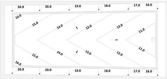
Now, here’s a sketch of a landfill single-cell design:
Obviously the chevron pattern!
Note the cell base area with elevation contours that resemble the chevron pattern, with the leachate collection pipe located along the centerline of the cell. The cell base area is sloping toward the leachate collection pipe to convey landfill leachate at the base to the pipe, then the pipe conveys the leachate to the leachate sump located at the low end of the pipe. The pattern at the base can easily be duplicated in either direction of the cell area, developing a multi-cell design resembling the chevron pattern shown above.
In this case, the straight lines connect the low points (representing leachate collection pipes) and the high points (representing the divider berms separating adjacent cells). The zig-zag lines in the pattern remind landfill engineers of the elevation contours for the landfill bottom design geometry.
Meanwhile, with the herringbone pattern, the adjacent “tiles” or rectangular shapes are in a perpendicular position to each other and do not resemble the zig-zag lines in the chevron pattern. The herringbone pattern cannot be representative of the elevation contours, leachate collection pipes, and the boundary lines between adjacent cells like the chevron pattern. Additionally, the angle of line segments in the zig-zag in the chevron pattern can vary to any desirable value, which allows representation of changes to the disposal cell base slope (an important parameter in landfill design). On the contrary, the tile position in the herringbone pattern has to maintain perpendicular angles throughout and therefore it loses the ability to represent various base slopes.
One may draw lines along interface boundaries of the herringbone features and come up with the chevron pattern. But why stretch the truth when the chevron is already clearly the pattern? It is not apparent how or why the herringbone association took hold in the first place, but it’s about time that changed.
Admittedly, it took nearly four years to scientifically support the validity of the Special Relativity Theory from the time it was published by Albert Einstein in 1916. And it took nearly 50 years to physically detect the existence of Higgs boson particle from the time it was theorized by Peter Higgs in 1964. So, I suppose we can wait for formal recognition of chevron designation for landfill design.
Why such a big deal!?
The chevron validation may be insignificant compared to the scientific validations of Einstein’s and Higgs’ work. For landfill engineers, attune to details, it could be considered big because anything new, and more accurate in the landfill design field is a cheering matter!
Throughout the history of science, new findings supported by scientific evidence have replaced prior theories or concepts when progress is desired. Change of the pattern association, in this case, may not qualify as a scientific finding; however, it is a clear and noteworthy correction to what landfill engineers have been using over the past many years.
About the Author:
Ali Khatami, Ph.D., PE, LEP, CGC, is a Project Director and a Vice President of SCS Engineers. He is also our National Expert for Landfill Design, Construction Quality Assurance, and Elevated Temperature Landfills. He has over 40 years of research and professional experience in mechanical, structural, and civil engineering.
State regulatory agencies normally require landfill slopes reaching final grades to close within a certain period. This requirement leads to closing landfill slopes in phases, normally referred to as partial closure. Generally, partial closures start from the bottom of the landfill slope up to a certain elevation, with geosynthetics in the final cover temporarily anchored along the partial closure’s sides and upper boundary. Engineers propose different designs for securing the lower boundary of partial closures at the bottom of the landfill slope. Some engineers propose an anchor trench outside the bottom lining system anchor trench to secure the final cover geosynthetics. Others specify welding the cover geomembrane to the bottom lining system geomembrane.
Anchor Trench for Final Cover Geosynthetics at the Bottom of the Slope
Experience with anchor trenches at the bottom of the landfill slope for the final cover geosynthetics has not been positive because of these issues:
Landfill gas may escape through the opening between the bottom lining system anchor trench and the final cover anchor trench.
Leachate seeps below the final cover geomembrane that reaches the bottom of the landfill slope may penetrate the landfill perimeter berm through the opening between the two anchor trenches.
High concentrations of landfill gas may be detected along the landfill perimeter berm at the location of the two anchor trenches during surface emissions monitoring.
If high leachate levels are developing inside the landfill cell, landfill leachate may escape through the opening between the two anchor trenches.
Welding of Final Cover Geomembrane to the Bottom Lining System Geomembrane
To eliminate the issues above, engineers weld the final cover geomembrane to the bottom lining system geomembrane for cases when there is a bottom lining system below the waste. The welding completely seals the landfill interior space from the outside environment and keeps regulated materials, such as waste, leachate, and gas, within the sealed system. Of course, the engineer should design proper means to address these behind the sealed system; designs may include:
A leachate toe drain system below the final cover geomembrane at the bottom of the landfill slope to collect and convey leachate seep liquids to the leachate collection system at the bottom of the landfill.
A suitable landfill gas collection system below the final cover geomembrane, at the lower boundary of the landfill slope, collects gases accumulating in the area.
This is an important consideration because the closest gas collection well may be over 250 ft. away, up on the slope.
A rainwater toe drain system above the final cover geomembrane, at the bottom of the landfill slope, collects and drains the water in the final cover geocomposite.
Leachate Toe Drain System (LTDS)
Leachate toe drain system is a concept originally developed by SCS and incorporated into landfill final cover designs over the past 20 years. Unfortunately, many solid waste engineers are unaware of the need for LTDS, so their designs lack this important feature. LTDS saves a tremendous amount of repair money in the long run by avoiding complications for landfill operators.
Rainwater Toe Drain System (RTDS)
A rainwater toe drain system removes water that moves laterally within the final cover geocomposite toward the slope’s bottom. The RTDS includes a perforated HDPE pipe encased in gravel and wrapped in geotextile. Also, install the RTDS on terraces along the depression on the interior side of the terrace. Along the landfill slope’s bottom, position the RTDS behind a HDPE flap welded to the final cover geomembrane. The RTDS is sloping with high and low points along the RTDS alignment. Lateral drain pipes located at low points remove water from the RTDS to the perimeter ditches.
Other designs involving extending the geocomposite to daylight at the slope surface cause problem such as those listed below:
Excessive vegetation impacts the opening of the geocomposite at the outlet edge.
Soil erosion from higher-ups clogs the opening of the geocomposite at the outlet edge.
Algae grow at the opening of the geocomposite at the outlet edge.
Gradual discharge of water from geocomposite softens the perimeter berm soils in the vicinity of the outlet edge.
Water percolates into the landfill perimeter berm and causes stability issues; and
A slippery surface develops along the outlet edge on top of the landfill perimeter berm, creating a health and safety issue for landfill personnel.
Similar issues can also occur at the outlet of such systems on landfill terraces, making the RTDS a superior design.
Landfill owners who are aware of the associated features mandate their inclusion to ensure their landfill final covers’ long-term superior performance.
About the Author:
Ali Khatami, Ph.D., PE, LEP, CGC, is a Project Director and a Vice President of SCS Engineers. He is also our National Expert for Landfill Design, Construction Quality Assurance, and Elevated Temperature Landfills. He has over 40 years of research and professional experience in mechanical, structural, and civil engineering.
It is not out of the ordinary to see several different landfill designers providing services at a specific site over many years. Each landfill designer brings his/her preferences and designs to the owner, depending on the urgency of the projects and the owner’s willingness to accept new concepts.
Experienced landfill designers review the prior history of design work at the facility and ensure that their new design work is compatible with previously developed cells and final covers. Lack of such due diligence could impede landfilling operations following implementation of the design with implications that may survive for many years to come at a high cost to the owner.
Proper due diligence may reveal issues that the owner may not be aware of. In such cases, the new landfill engineer attempts to explain the observed issues from a previous design to the owner’s attention during one or more meetings or through a narrative report including documentation of the issues and measures to address each issue. The owner may accept or reject the technical matters brought to their attention by the new landfill designer. If accepted, authorize the new design engineer to prepare proper plans and details, and assist in retaining a contractor to fix noted problems. If rejected, the new landfill engineer can feel confident he/she is professionally conducting himself/herself considering the ethical obligations in his/her profession.
If the new landfill engineer had not brought up issues discovered during the due diligence, the owner could blame the new designer claiming that he/she should have known better. Such situations do not get resolved easily and could lead to another change in the design team.
The cost of performing thorough due diligence may not be in the first task order’s budget. However, it will certainly pay off over time with back-to-back task orders from the owner when confidence n the designer’s capabilities build over time.
Changes to the landfill personnel may occur similar to any other organization. Landfill general managers, operation managers, site engineers, or compliance engineers may leave, and the position filled by a new person who has no site familiarity or history. These types of rotations can provide the opportunity for inexperienced landfill designers to influence the site’s long-term plans. Mistakes by inexperienced designers can last decades in some instances, while new and remaining personnel must deal with the consequences.
SCS’s project management protocols require project managers to constantly learn about the site’s history and review documents representing the backbone of the facility development over the long-term life of the site to the present. This type of continual learning of important matters and minute nuances of the site history equips a project manager to address technical and permitting issues based on knowledge of prior work performed at the facility. Implementation of new ideas based on prior knowledge of the site history is considered the backbone of properly managing projects and serving the client in consideration of their business priorities.
Past knowledge comes from documents prepared by prior designers and knowledge of site personnel who have been working at the site for a long time. Competent engineers welcome opportunities to interview and discuss site history, especially with long-term site personnel. The knowledge these people carry with them is not found in any document that the designer, if lucky enough to get his/her hands-on, may obtain by review. The knowledge of the changes to existing systems during original construction and a later date, which may not have been documented, can lead the engineer to concepts that otherwise would not have been envisioned without the long-term employee’s information of the site.
As a landfill designer, never assume that you know everything about the site; there are always things hiding deep in the landfill that you may learn.
About the Author:
Ali Khatami, Ph.D., PE, LEP, CGC, is a Project Director and a Vice President of SCS Engineers. He is also our National Expert for Landfill Design, Construction Quality Assurance, and Elevated Temperature Landfills. He has over 40 years of research and professional experience in mechanical, structural, and civil engineering.
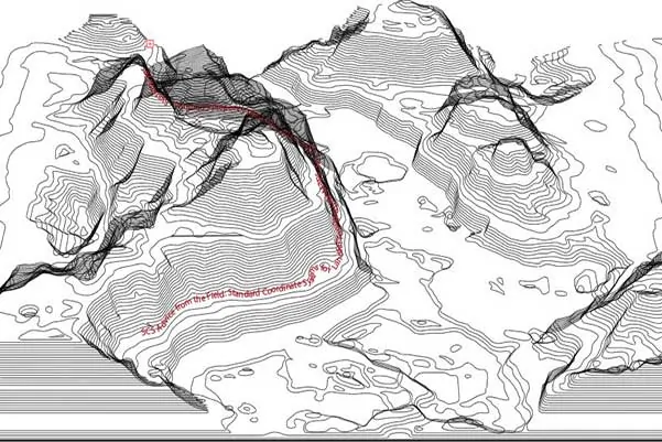
Landfill engineers rely heavily on topographic maps in their design work. Topographic maps present elevation contours, known as contour lines, for changes in the ground surface. Surveying companies create contour lines by performing land surveys, Light Detection and Ranging (Lidar) surveys, or aerial mapping. In all cases, the topographic maps are generated based on a standard coordinate system.
Basing horizontal systems on geodetic coordinates worldwide, they may be updated every few years or decades. An example of the horizontal coordinate system is the North American Datum (NAD). A datum is a formal description of the Earth’s shape and an anchor point for the coordinate system. Using the NAD system, engineers can make horizontal measurements in consideration of the anchor point information.
NAD 27 and NAD 83 are two versions of the NAD system with slightly different assumptions and measurements. A point with specific latitude and longitude in NAD 27 Datum may be tens of feet away from a point with similar latitude and longitude in NAD 83 Datum.
The latitude and longitude of an initial point (Meads Ranch Triangulation Station in Kansas) define the NAD 27 Datum. The direction of a line between this point and a specified second point and two dimensions define the spheroid. Conversely, NAD 83 Datum uses a newer defined spheroid, the Geodetic Reference System of 1980 (GRS 80). GRS 80 is an Earth-centered or geocentric datum having no initial point or initial direction.
Similarly, vertical systems provide surveyors the means to measure vertical measurements based on a standard system. Examples of the vertical datum are the National Geodetic Vertical Datum 1929 (NGVD 29) and North American Vertical Datum 1988 (NAVD 88).
Using topographic maps, solid waste engineers pay special attention to the standard coordinate system used for generating the topographic map made available to them for their design work. Engineers will want to check for additional topographic maps using another Datum for the same site. Checking eliminates the possibility of discrepancies in the design documents.
Typically, the standard system set for a landfill site remains unchanged for consistency among topographic maps generated over the years. If the standard system must change, document the conversion making it available to the solid waste engineers working at the site. The conversion information is valuable for converting engineering plans to prevent the older plans from becoming obsolete and unusable for practical engineering work.
A solid waste engineer that begins work for the first time at an existing landfill site pays special attention to the standard system (horizontal or vertical). The engineer wants to ensure the time spent producing design documents and plans aren’t wasted. For optimum efficiency, landfill owners contracting with new solid waste engineers should provide conversion information from the old to the new system upon the contract’s commencement.
The United States National Spatial Reference System NAD 83(2011/MA11/PA11) epoch 2010.00, is a refinement of the NAD 83 datum using data from a network of very accurate GPS receivers at Continuously Operating Reference Stations (CORS). A new Global Navigation Satellite System (GNSS) will replace the National Spatial Reference System NAD 83 and the NAVD 88 in 2022, according to the National Geodetic Survey Strategic Plan 2019-2023. The GNSS will rely on the global positioning system and a gravimetric geoid model resulting from the Gravity for the Redefinition of the American Vertical Datum (GRAV-D) Project. The new systems’ intention is easier access and maintenance than NAD 83 and NAVD 88, which rely on physical survey targets that deteriorate over time.
Solid waste engineers should be aware of the upcoming changes to adapt site designs as necessary and to check with landfill owners and operators to check for any implementations at their facilities.
About the Authors:
Ali Khatami, Ph.D., PE, LEP, CGC, is a Project Director and a Vice President of SCS Engineers. He is also our National Expert for Landfill Design, Construction Quality Assurance, and Elevated Temperature Landfills. He has over 40 years of research and professional experience in mechanical, structural, and civil engineering. Dr. Khatami has been involved for more than 30 years in the design and permitting of civil/solid waste/environmental projects such as surface water management systems, drainage structures, municipal solid waste landfills, hazardous solid waste landfills, low-level radioactive waste landfills, leachate and wastewater conveyance and treatment systems, gas management systems, hazardous waste impoundments, storage tank systems, waste tire processing facilities, composting facilities, material recovery facilities, landfill gas collection and disposal systems, leachate evaporator systems, and liquid impoundment floating covers. Dr. Khatami has acquired extensive experience and knowledge in the areas of geology, hydrogeology, hydrology, hydraulics, construction methods, material science, construction quality assurance (CQA), and stability of earth systems. Dr. Khatami has applied this experience in the siting of numerous landfills.
William Richardson, EIT is Project Professional at SCS, and part of our Young Professionals organization. Will has two years of experience with landfill design projects, including permit modifications and siting requirements. He is currently working in Virginia Beach under the tutelage of Dr. Khatami.
Landfills are large and dynamic systems that can take several decades to develop. Unlike many other infrastructure projects that have a beginning and an end to the construction of the project, landfills constantly grow and change due to many factors, including but not limited to:
The type of waste stream delivered to the site;
Type of operations carried on at the site;
Operator’s experience and operational preferences;
Capital flow into the site;
State and local regulatory changes;
Engineer’s recommendations;
The rate of development around the site;
Interactions with local communities around the site;
Agreements with environmental groups; and
Political will and the extent of support by politicians.
From an engineering perspective, it is very common to see changes to the engineering team over time. Each team brings about their ideas and preferences to the operator, and if they present technically competent and economically solid ideas, they can change the course of the landfill development. The course change could be shaped by what will get constructed, how it will get constructed, when it will get constructed, and what sequence it will get constructed. In most cases, the owner is in the loop, but the owner may not be intimately familiar with the nuances that such designs and modifications entail. Therefore, the owner may not necessarily realize hidden problems or mishaps that may happen in the future, which could be prevented by the engineer at an earlier stage of work.
Competent engineers starting work at an existing landfill site for the first time need to review years of data to become familiar with the history of the site before they can begin design work. The history of the site involves, but is not limited to, land use approvals, permitting, designs, modifications, environmental impacts, subsurface conditions, environmental improvements, leachate and gas collection and disposal, existing and future planned developments, operation requirements, and many other features that vary from site to site. Without such knowledge, the engineer is working in the dark without the owner’s knowledge that the engineer’s path lacks familiarity with details. Work products generated by an engineer with limited familiarity with the site are, at best, not reliable. Even potentially having significant impacts on the owner to fix issues that otherwise are preventable with sufficient due diligence.
For example, tasking an engineer to close a portion of the landfill, the engineer must investigate any plans set for landfill development, in the area planned to close. The engineer and owner can discuss any problems discovered by the engineer’s early due diligence, and solutions will be developed and adopted to address issues during the design. This level of due diligence provides the opportunity to generate sound designs and develops a level of confidence in the engineer in the mind of the owner.
SCS landfill design professionals train regularly to be thorough and comprehensive in their familiarization with a site. They spend significant effort to foresee potential problems that might arise many years down the road and find solutions for them now.
About the Authors:
Ali Khatami, Ph.D., PE, LEP, CGC, is a Project Director and a Vice President of SCS Engineers. He is also our National Expert for Landfill Design, Construction Quality Assurance, and Elevated Temperature Landfills. He has over 40 years of research and professional experience in mechanical, structural, and civil engineering. Dr. Khatami has been involved for more than 30 years in the design and permitting of civil/solid waste/environmental projects such as surface water management systems, drainage structures, municipal solid waste landfills, hazardous solid waste landfills, low-level radioactive waste landfills, leachate and wastewater conveyance and treatment systems, gas management systems, hazardous waste impoundments, storage tank systems, waste tire processing facilities, composting facilities, material recovery facilities, landfill gas collection and disposal systems, leachate evaporator systems, and liquid impoundment floating covers. Dr. Khatami has acquired extensive experience and knowledge in the areas of geology, hydrogeology, hydrology, hydraulics, construction methods, material science, construction quality assurance (CQA), and stability of earth systems. Dr. Khatami has applied this experience in the siting of numerous landfills.
William Richardson, EIT is Project Professional at SCS, and part of our Young Professionals organization. Will has two years of experience with landfill design projects, including permit modifications and siting requirements. He is currently working in Virginia Beach under the tutelage of Dr. Khatami.
With the proper design and planning, partial final covers can provide multiple benefits and long-term performance from the active life and well beyond.
There are several hundreds of Municipal Solid Waste (MSW) landfills in the United States. Many of these landfills are anticipated to remain active for decades to come, and Federal and state rules require slopes reaching permitted final elevations to be closed within 180 days. This means partial closure of slopes is part of the operational requirements of MSW landfills.
Federal and State Rules
Subtitle D of the Resource Conservation and Recovery Act (RCRA), enacted on October 21, 1976, requires the final cover of MSW landfills to include a barrier layer with hydraulic conductivity that is substantially equivalent to or less than the hydraulic conductivity of the bottom liner. State-level regulations developed following the enactment of the federal law also required similar standards for MSW landfills. Many states, pursuing the federal guidelines, require at a minimum, the bottom lining system of MSW landfills include at least one primary barrier layer consisting of Polyvinyl chloride (PVC), high-density polyethylene (HDPE), linear low-density polyethylene (LLDPE). Naturally, the final cover barrier layer should also be PVC, HDPE, LLDPE as well.
According to the Federal and state regulations, following the completion and closure of a MSW landfill, the facility owner maintains the landfill for a minimum of 30 years beyond the final closing date. Extension of the long-term care period beyond the 30-year post-closure period is a hot subject among solid waste professionals. Some states have already implemented matrices for such time extensions; it is anticipated that the remaining states will require similar extensions for MSW landfills over the next several years. Even if regulatory agencies approve completion of the post-closure period for a specific landfill, the landfill’s final cover system is expected to perform for many more years to come. Otherwise, environmental issues associated with a lack of performance may force the regulatory agency to spend money for repairs no longer available through a financial instrument.
Long-Term Performance Designs
For the past few decades, SCS has specifically designed and permitted final cover systems with special features to prolong the final cover system’s performance beyond the post-closure period of the landfill. The final cover system designs:
Maximize available airspace in the landfill,
Simplify waste placement in the vicinity of the exterior landfill slopes,
Simplify stormwater management components over landfill slopes,
Effectively collect and remove rainwater percolating through the final cover soils,
Collect lateral leachate seeps below the final cover barrier layer, and
Effectively encapsulate landfill gas at the landfill perimeter.
Less Maintenance
The first partial final cover with these features was constructed in 1998, and since then, many more partial closures with these types of features have been constructed. All partial closures are performing satisfactorily without failure. Regular maintenance of the final cover vegetation and occasional cleaning of drainage swales, which are common maintenance activities, have been the only measures taken by the operators of the facilities with these final cover systems.
The features incorporated into the final cover systems were:
Straight 3H:1V slopes to the top of the landfill with no benches or terraces, providing benefits such as maximizing airspace; eliminating complications during filling of the landfill near exterior slopes; allowing final surface water drainage swales to be constructed during the construction of the final cover which provides flexibility for the swale locations, swale slopes, drainage points of swales on the slopes; and downchute pipes that do not require complicated geometric features at the point of connection to drainage swales on the slope;
A leachate toe drain system (LTDS) collecting and disposing of leachate seeps below the final cover geomembrane reaching the bottom of the landfill slope; and
A rainwater toe drain system (RTDS) collecting and draining out of the final cover the rainwater that percolates through the final cover reaching the cover system geocomposite drainage layer.
The features above have financial, performance, and stability benefits for the facility for many years to come. So far, such final covers have been constructed on 3H:1V slopes as long as 550 ft. in length with no terraces. Several of the completed final covers were partial closures on a 3H:1V slope, where the next phase was constructed directly above a previous phase with the two phases tied together at the phase boundary.
Proper design and planning for the construction of partial final covers are significantly important for the long-term performance of landfills during the active life, post-closure period, and beyond.
Want more advice from our designers? Select articles and blogs for further reading:
The large majority of landfills in the country show no signs of special conditions indicating too much heat. Under certain conditions, elevated temperatures may occur inside a landfill, and the excess heat changes the character of chemical reactions taking place in the landfill, such as the decomposition process of the organic matter. Read and follow SCS Advice from the Field blogs for landfill best management practices.
SCS Advice from the Field
Landfill operators have known about elevated temperature conditions in landfills for nearly a decade. Some operators have already incurred numerous expenses to control adverse environmental and operational issues at these landfills, and some operators have set aside large amounts of money in their books to address future liabilities associated with such landfills. Due to the complexities of controlling elevated temperature conditions and the compliance issues arising from such conditions, it can force operators to temporarily, or permanently close their landfills.
Can design address elevated temperature conditions?
The operators of larger landfills have been monitoring and analyzing data to identify triggering factors, while others continue controlling the environmental impacts. Environmental Research & Education Foundation (EREF) initiated several research projects to identify the triggering factors with the excellent scientific work of highly qualified researchers. These are on-going projects.
In the meanwhile, operators of larger landfills are developing strategies, basing strategic-decisions on the data and conditions collected during operations over long periods. After analyses, they have the means to reduce the impacts by making changes in their operations and landfill designs. The most effective changes include eliminating certain waste types from the waste stream and improving the movement of liquid and gas through the waste column with new designs.
Are design innovations consistently implemented?
The pioneering designs feature preventative measures, intending to avert the formation of elevated temperature conditions in future disposal cells. Implementing these new design features requires careful consideration and functional analyses, as some of the recommendations can be costly, affecting the bottom line. The urgency in controlling compliance issues associated with elevated temperatures and the associated financial impacts of such conditions objectively prescribe that local managers work closely with their designers and field expertise to bring non-compliance issues under control.
Is this an executive risk management strategy?
Until the on-going research more clearly identifies the triggering factors and the means to prevent the development of elevated temperature conditions, it seems logical to invest in implementing preventative measures that are currently available. When more research results are accessible, then the local managers will be able to make decisions that are even more informed. Those wanting to address the likelihood of future liabilities proactively will need executive-level funding and superior technical support, all of which are possible.
Is there much sharing of newer designs and strategies within the solid waste industry?
Yes, there is a fair amount of collaboration among the technical community and within solid waste associations. Most operators share their preventative designs within the engineering community and help contribute to funded research. Their actions and results will help to strengthen an industry application until such time that research results and the means to prevent the development of elevated temperature conditions are well understood. We all know that progress in technology and science depends on sharing new knowledge.
Let’s continue with the combination of serious research, innovative designs, proactive operational changes, and sharing knowledge among our industry professionals that will lead to more precise solutions in the near future. Here are a few resources available now:
About the Author: Ali Khatami, Ph.D., PE, LEP, CGC, is a Project Director and a Vice President of SCS Engineers. He is also our National Expert for Elevated Temperature Landfills, plus Landfill Design and Construction Quality Assurance. He has nearly 40 years of research and professional experience in mechanical, structural, and civil engineering.
On July 7, 2020, the City of Brownsville Commission approved a recommendation by the Engineering and Public Works Department to continue an existing multi-year partnership with SCS Engineers. SCS is an environmental consulting and contracting firm that will serve the City for an additional five years. The environmental contracts support the Landfill Gas Collection and Control System (GCCS) expansion and provide landfill engineering, compliance, monitoring and operations assistance.
Project Director, J. Roy Murray, an SCS vice president, and the team’s principal consulting engineer will continue to serve the City’s citizens and staff. Mr. Murray has decades of experience in civil and environmental permitting, design, and construction at municipal solid waste landfills (MSW), including 20 years serving the Brownsville Landfill. Mr. Murray states:
The City staff and Commission continues to entrust SCS Engineers to help the landfill staff with the safe, efficient, and compliant operation of the landfill. We are honored by their trust. The City of Brownsville MSW Landfill Operations team serves the City well. The facility is the primary solid waste disposal site for surrounding communities, carefully engineered and maintained regularly even during severe weather and now a pandemic. The forethought of the Landfill Division, their leadership, and innovative practices provide the citizens with stellar services while protecting the environment.
The initial installation of the City Landfill’s Gas Collection and Control System (GCCS) completed in 2011, was part of an Energy Efficiency and Conservation Block Grant the City received from the American Recovery and Reinvestment Act of 2009. SCS Engineers assisted with the application process, and as a result of the collaboration, the City received a $1.7 million grant to install a landfill gas collection system at the landfill. With GCCS operation, the City has reduced its greenhouse gas emissions. The landfill infrastructure and emission reductions were voluntary at the time, but the Texas Commission on Environmental Quality (TCEQ) Air Quality rules and regulations, and EPA’s New Source Performance Standards, now require them.
The Gas Collection and Control System consists of 16 landfill gas extraction wells and currently provides coverage of 32 acres of the City Landfill’s disposal footprint. The City plans to expand the GCCS during 2021, to support landfill’s growth and stricter air permit regulations. The expansion includes 38 additional wells covering 120 acres of the landfill footprint. The new wells will integrate with the collection system and integrate with liquids management, leachate control, and stormwater systems, among others.
About SCS Engineers
SCS Engineers’ environmental solutions and technology are a direct result of our experience and dedication to solid waste management and other industries responsible for safeguarding the environment. For more information about SCS, please follow us on your preferred social media channel, or watch our 50th Anniversary video.
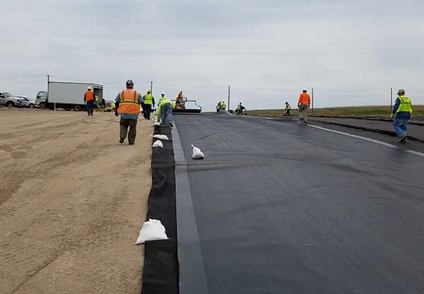
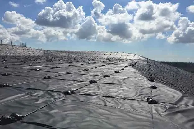
Landfill slopes that have reached final grades, or will receive waste in the distant future have maintenance challenges. Environmental elements continually affect surface conditions, and remedial work is required routinely to prevent negative outcomes of exposed slopes. Consider using a geomembrane temporary cap to address much of the maintenance. Here’s a list showing how the cap can help:
Landfill Maintenance Challenge
Washouts due to stormwater runoff
Need to establish a vegetative cover
Maintain grass regularly
Leachate seeps appearing without warning
Landfill odors after storms
Surface disturbance from gas lines or associated construction
Leachate generation from rainwater percolation
With Geomembrane Temporary Cap
No washouts – sheet flow of stormwater runoff over the geomembrane
No need for a vegetative cover
No mowing, or cutting paths to read a well
Leachate seeps diminish with a temporary impermeable layer
Additional barrier to control landfill odors
Easily place gas lines above the geomembrane
Less percolation equates to less leachate generation from the capped area
The significant maintenance savings by using a temporary cap make the payoff period for the investment attractive. Based on my experience and site variations, the return on investment is usually three to six years. The period is considerably shorter if your landfill does not have a leachate disposal or treatment system, or deep injection well. The difference is the high cost to have the leachate hauled away.
Temporary caps potentially reduce routine maintenance work, leaving operation staff available for other tasks. The cap provides peace of mind that slopes remain in compliance; regulators don’t need to report non-compliance conditions of exposed slopes during inspection events.
After completing 25 temporary cap projects in the U.S. Southeast alone, we highly recommend using a thick geomembrane. It’s tempting to try to save money using a thinner geomembrane, such as 12 mils or 20 mils, but these can damage more easily and will negatively affect your return. The majority of SCS clients chose to use the recommended 40 mils thick geomembrane, which will survive severe weather conditions.
Ballasting the geomembrane and using the right materials for ballasting is significantly important. We recommend using ultraviolet (UV) resistant rope and sandbags, a tried and true system. UV resistant straps are a decent replacement for ropes. Anchoring mechanisms are also important. We typically recommend using 4×4 treated wood posts at 10-ft spacing, installed in anchor trenches, and tied to ballasting ropes. Depending on the site and operator’s preference, the supporting architecture may be to lay the post horizontally, while tied to the ballasting ropes, at the bottom of the anchor trench buried in the anchor trench’s backfill material.
Over the years, landfill operators have experienced the savings and value that temporary caps bring to landfill operating budgets, and we’re placing more temporary caps every year. If considering this option, SCS can assist you by evaluating the slopes at your site for the caps. We’ll also prepare estimates for the purchase of material and installation costs and estimated time of recovery for your project.
About the Author: Ali Khatami, Ph.D., PE, LEP, CGC, is a Project Director and a Vice President of SCS Engineers. He is also our National Expert for Elevated Temperature Landfills, plus Landfill Design and Construction Quality Assurance. He has nearly 40 years of research and professional experience in mechanical, structural, and civil engineering.
Landfills located in areas with high precipitation usually experience leachate seeps on slopes. The location of leachate seeps varies, and the reason behind the seeps appearing on the slopes varies as well.
As long as the slope does not have its final cover, you can attempt to control leachate seeps no matter where the seep location. There are many remedies known to landfill operators for controlling seeps before the final cover, but leachate seeps below the final cover are not controllable. The reason is the seeps are out of reach, and you have no means to control or mitigate the situation. The only potential solution is a seep management system built under the final cover geomembrane at the time of final cover construction.
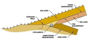
For landfills with slopes extending up to the top of the landfill without terraces, construct a leachate toe drain system (LTDS) at the toe of the slope adjacent to the landfill perimeter berm. The design will collect and convey liquids emanating from seeps further up on the slope (below the final cover geomembrane) to the leachate collection system. See Figure 1.
Figure 1: A typical design for the LTDS at the toe of the slope (SCS Engineers).
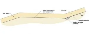
For landfills with terraces on the slope, construct LTDSs at every terrace. Best practices call for the location at the toe of the slope, above the terrace, the lowest point of that slope. Consequently, the terrace width prevents seep liquids from flowing further down the slope, and the LTDS at the terrace prevents the accumulation of leachate behind the final cover geomembrane at the interior line of the terrace. See Figure 2.
Figure 2: A typical design for the LTDS at a terrace (SCS Engineers).
At the lowest point of the terrace, locate a downspout to convey liquids to the leachate collection system at the bottom of the landfill. You will also need a LTDS at the toe of the slope adjacent to the landfill perimeter berm, as discussed above. You may connect the terrace downspouts to the LTDS located adjacent to the perimeter berm to drain the liquids collected at terraces.
To prevent erosion of fines by small streams of liquids flowing down the slope below the final cover geomembrane use this best practice. This design will prevent depressions forming in the top surface of the final cover. First, place a LTDS geocomposite panel from the source of any leachate seep that you identify on the slope right before the construction of the final cover. Connect the panel to the LTDS pipe-gravel burrito at the terrace or perimeter berm. This solution provides a preferential path for liquids coming out of the seep without causing erosion. See Figures 1 and 2.
Place the LTDS geocomposite below the LTDS burrito when simultaneously constructing the burrito and the LTDS geocomposite. When constructing the LTDS burrito ahead of time, place the LTDS geocomposite above the burrito later. In either case, the contact area between the LTDS burrito and the LTDS geocomposite must be free of soil, which could impede the free flow of liquids to the LTDS burrito.
SCS has a 20-year record of accomplishment solving leachate seeps below the final cover geomembrane. Feel free to contact our landfill designers for advice.
About the Author: Ali Khatami, Ph.D., PE, LEP, CGC, is a Project Director and a Vice President of SCS Engineers. He is also our National Expert for Landfill Design and Construction Quality Assurance. He has nearly 40 years of research and professional experience in mechanical, structural, and civil engineering.
You are about to leave the SCS Engineers’ website and be directed to an external third-party site, ICIMS. SCS is not responsible for the collection and use of information on the ICIMS site, which is governed by its own privacy practices, not this Notice. We encourage you to review their privacy notices for additional information. Do you want to continue?
To provide the best experiences, we use technologies like cookies to store and/or access device information. Consenting to these technologies will allow us to process data such as browsing behavior or unique IDs on this site. Not consenting or withdrawing consent, may adversely affect certain features and functions.
✕
We use cookies and similar technologies for the following purposes:
Cookie usage
We use cookies to ensure the basic functionalities of the website and to enhance your online experience.
You can choose for each category to opt-in/out whenever you want.
Functional
Always active
The technical storage or access is strictly necessary for the legitimate purpose of enabling the use of a specific service explicitly requested by the subscriber or user, or for the sole purpose of carrying out the transmission of a communication over an electronic communications network.
Statistics
The technical storage or access that is used for statistical and/or tracking purposes.The technical storage or access that is used exclusively for anonymous statistical purposes. Without a subpoena, voluntary compliance on the part of your Internet Service Provider, or additional records from a third party, information stored or retrieved for this purpose alone cannot usually be used to identify you.
Marketing
The technical storage or access is required to create user profiles to send advertising, or to track the user on a website or across several websites for similar marketing purposes.


 William Richardson, EIT is Project Professional at SCS, and part of our Young Professionals organization. Will has two years of experience with landfill design projects, including permit modifications and siting requirements. He is currently working in Virginia Beach under the tutelage of Dr. Khatami.