Managing Liquids Extracted From Landfills
Environmental engineers specializing in landfills can successfully design disposal sites and infrastructure to mitigate how much liquid enters the waste matrix. If liquids do infiltrate the waste or gas extraction system, these professionals effectively capture and direct them to the bottom of the leachate collection system, where it belongs.
But success brings different challenges following extraction.
“You pull liquid and leachate from your landfill and landfill infrastructure, but now the question is, where do I send it? And there are no simple solutions. It’s a hard wastewater stream to manage, especially as operators grapple with increasing volumes and strength,” says Bob Dick of SCS Engineers.
As precipitation increases in many regions and operators take in wetter special wastes like sludges, finding an economically and logistically viable means to offload leachate quickly is daunting. Tightening regulations around what publicly owned treatment works (POTW) will accept adds even more pressure.
There are three main issues resulting from higher leachate quantities and its quality. Those issues are:
Storage tank capacity
“I have clients with two tanker trucks cycling 24 hours a day, taking leachate to the POTW, but they still can’t keep up with their volumes. So, they can’t be as aggressive as they want in moving it out. It’s coming out of their landfills, and they have nowhere to store it all,” Dick says.
Transportation limitations
Operators can’t transport leachate fast enough to keep pace with steadily accumulating volumes. It takes time to load tanker trucks, drive long distances, return, and repeat the process, Dick says. Even finding a facility to accept it can be difficult, compelling some of them to ship it on barges or haul it by rail—costly processes.
Wastewater treatment plant issues
Increasingly, POTWs faced with permit restrictions limit how much leachate they will take or refuse altogether, either because of the volume, quality, or characteristics.
This problem magnifies as high concentrations of several specific constituents are now often seen, including high ammonia and nitrogen. Other offenders increasingly coming into play are total suspended solids (TSS) such as clay, sand, and silt and total dissolved solids (TDS), smaller particles than TSS, including minerals and microorganisms.
Mixing leachates adds complexity
Some liquids inevitably make their way into gas extraction wells above the leachate collection system. A common solution is pumping them out so gas can enter the pipes and injecting them into nearby leachate piping. There it mixes with leachate from the bottom of the landfill.
This method may solve one problem but presents another challenge: gas dewatering liquid is a much higher strength than filtered leachate at the bottom. Mixing them could disrupt the POTW’s system due to biological changes in the material, explains Eric Peterson of SCS Engineers. He’s seen this headache escalate as POTWs adopt more sophisticated technology; it treats most leachate better, but liquids from gas wells interfere with the newer process.
“We’ve seen POTWs who refuse the liquid because it’s stronger than previously, and the plant can no longer manage it. We have also seen upsets at on-site treatment plants that may be designed for the leachate conditions at the bottom of the landfill; now they must deal with a more polluted gas dewatering liquid,” Peterson says.
Ensuring this liquid can work in either facility type requires pretreatment. Even with the more benign liquid extracted from the bottom and sent to the force main, pipes are prone to clogging, requiring due diligence in preventative maintenance.
Strategies to manage extracted leachate
Currently, three options offer alternatives to the time and money intensive process of trucking high volumes long distances:
Leachate evaporator
This system heats liquids and evaporates the water molecules, reducing leachate volume by 70 to 90 percent, enabling operators to return the sludge-like residual to the landfill. Managing liquids on-site leveraging this technology eliminates dependency on drivers and the POTW.
“The idea is that the residual is small enough that you can effectively manage it in your landfill. But regulations may require another step to solidify the liquid residue,” says Zach Mahon of SCS Engineers.
Solidification of waste
Solidifying high-strength liquids entails mixing them with an amendment such as sawdust or lime that adsorbs them, removing them from the water phase, and strengthening them to dispose of in the landfill safely.
But this process is often a temporary fix. “You are typically just imposing a management technique that slows movement,” Dick says.
On-site leachate treatment
This option can clean the material to POTW-acceptable standards or enable it to discharge into the environment safely. Reverse osmosis (RO) is a common treatment of choice, where leachate flows through a membrane, separating contaminants that collect in a solution. RO can reduce contaminated water by 90 percent, typically rendering it clean enough to discharge directly to surface water with appropriate permits. Or, it can be discharged to the city sewer, eliminating the permitting step.
Mahon recently assessed all three options for a Midwestern client and a fourth solution that he believed fit this landfill’s particular needs. The operator’s 20,000-gallon tank was filling up so fast that it had to be hauled to the POTW nearly daily.
“The quality and volume were acceptable to the POTW; it was just an operational issue for the landfill. So, the solution is to install a force main that automatically pumps directly to the POTW, solving the challenges of scheduling trucks and drivers, quickly loading and unloading the vehicles,” Mahon says.
His team’s design enables the addition of RO should regulators’ requirements change or the POTW plant intensifies its discharge limits.
Still, solutions continue evolving. Landfill operators work with liquids management experts to keep up with the latest proven technologies. Many promising solutions are on the horizon, but you need a proven solution when investing capital.
Dick says the best defense is to remain proactive. Even with careful planning, some liquid will contact waste and become leachate. The best course is for robust engineering designs and sound operational practices to minimize leachate to the greatest extent possible.
– – – – –
There’s science, engineering, and careful maintenance happening inside and outside of a landfill, but it’s all there to capture emissions. We thank landfill owners and operations teams across North America for strategically managing landfill system integration and running these complex systems. These well-trained and educated teams include field technicians, landfill and environmental engineers, geologists, technologists, and specialized operations staff, to name a few. They work hard and smart to make sure each landfill remains a good neighbor while delivering essential services.
Slope failure
Side slope failures are not common but, depending on circumstances, can be catastrophic. When they happen, wet waste and soil that hold up the walls are often the leading catalyst. When moisture content increases, the friction angle (the angle at which waste is stable) decreases, and waste and soil slide down the hill.
Keeping a close watch for warning signs and taking proactive measures even before they emerge are landfill operators’ greatest defenses against disastrous failure; once the slope moves, it’s nearly impossible to stop it.
One general guideline is to monitor landfill liquid levels. Regulations require no more than 12 inches of liquid at the bottom of the site. An exceedance will reduce the slope stability significantly. But there are plenty more strategies to stay ahead of the curve and prevent major issues.
Three primary types of slope failures
The primary failures are circular, block-type or wedge, and veneer. Veneer failure is confined to the final geomembrane cover system; it’s minor and fixable, says James Law of SCS Engineers, an expert in geotechnical engineering.
Circular failures occur in the waste mass and affect the entire slope. In most cases, they are relatively minor, remaining near the mound’s surface. Less commonly, circular failures occur deep in the mass, which are major events.
“In either scenario, circular failures occur when the waste mass is uncompacted. It’s less dense and therefore weaker and susceptible to failure,” Law explains.
Block failure can be complex. It begins at the crest and descends to the bottom liner system, where the failure ultimately occurs. How it happens is there are multiple interfaces of soil and geosynthetic material that each contribute to a weakening zone of material at the bottom. That’s when a failure occurs, and it is serious.
Law advises operators to use a vetted engineering analysis to avoid block failure. “This analysis enables us to define the sheer strength of the interfaces at the bottom of the landfill to ensure sufficient resistance against failures and select soil or geosynthetic layers to accomplish this properly,” he says.
Early signs of failure and next course
Early signs of a failure of any type are tension cracks near the crest of the slope that runs parallel to the structure’s crestline. Especially lookout for an accelerated cracking pace, advises Bob Dick of SCS Engineers.
There may also be a barging or raising of the ground near the lower part of the slope or at the toe, indicating that the slope has moved.
Don’t simply fill in the tension cracks and walk away, Dick and Law advise.
“The chance is that they will reappear, especially during wet seasons. And each time they emerge, they will get worse. Eventually, the whole slope will collapse without proper attention,” Law says.
Once warning signs emerge, the best course of action is to bring in a geotechnical expert with landfill design expertise to analyze and set up instrumentation to monitor movement closely. That expert analysis will determine whether the slope failure is within the waste at the surface or the bottom of the landfill.
If it’s shallow within the waste, operators can be confident the integrity of the liner and collection system is not compromised. They can then turn their attention to addressing the material moving down the hill. But a failure deeper in the mass calls for immediate action to deal with complex, interacting systems at the bottom of the landfill.
Measuring slope movement
Settlement monuments and inclinometers— determine if the slope is moving, the location, and the direction of that movement. The settlement monument is a concrete block that gauges vertical and lateral movement at the surface, determining if and to what degree the surface dropped. The inclinometer is a PVC pipe installed below ground in the waste mass to measure the lateral movement of the entire slope.
Operators can also use a measuring instrument to gauge liquid above the liner, typically through a leachate collection clean-out pipe.
“If it is slowing, it may stop, but normally, nothing can stop it once it starts. We need to measure systematically to know if it’s accelerating; you have to get off the slope if it is. It’s not safe anymore. But these instruments could help save lives or equipment if they detect early signs of failure,” Law says.
Best practices to stay ahead of the curve
If the movement is very slow or stopped, landfill engineers can improve its stability by flattening or removing the upper portion of the slope. Removing this impervious surface increases safety by decreasing the weight of soil and waste pushing downward.
Another important proactive practice is installing a sump with a pump system to remove liquid and ensure it is low.
Leachate seeps
Leachate seeps are another ongoing challenge that relates to slope conditions. These breakouts happen when saturated waste becomes impermeable. Unable to penetrate, leachate can’t travel its intended route: straight down through the waste mass to the bottom of the landfill. With nowhere else to go, it runs horizontally and comes out the surface of the side slopes.
Uncontrolled seeps can be a big problem. They are a source of odors, can cause erosion, and the leachate can contaminate groundwater if it infiltrates stormwater.
Leachate can also seep below the final cover, causing a different set of problems: a pool of leachate at the toe of the slope that continues to grow. And slope instability due to excess moisture under the final cover geomembrane at the toe of the slope.
“Seeps indicate something is going on behind the slope. They typically are a condition tied to landfill operations. And it takes a lot of practice and planning to prevent or manage them,” Law says.
Some best practices are to break up daily covers before moving to the next cell. Operators may trench it or reuse it. Ultimately removing the impermeable surface enables leachate to drain straight down to the collection system.
Using plants and trees may also serve as a preventive measure. Their root systems can help secure the soil and minimize erosion and runoff depending on plant type.
In the case of an active seep, operators typically excavate a pit at its origin to encourage leachate to travel vertically to the drainage layer. The pit is backfilled with stone surrounding a perforated pipe, covering the structure with low-permeability soil. This practice usually proves successful as a first corrective action, Dick says.
But continuous, pervasive flow calls for more aggressive action. Dick advises in this scenario, operators may need to install perforated pipes with a pump in the stone excavation. This rock sump is a more substantial measure for when a long-term solution is needed, though it requires operational upkeep.
Whether a leachate stone pit is sufficient or whether the sump is also needed depends on the quantity of leachate seeping out and its frequency. Specifically, whether seeps occur only during precipitation or are continuous, Dick says.
Leachate seeps can tie to slope stability issues, particularly when excess moisture accumulates in the material under the final cover geomembrane at the toe of the slope.
Preventing leachate outbreaks and the overall job of maintaining strong, secure slopes comes back largely to managing liquids efficiently and proactively. It’s about preventing problems in the first place.
– – – – –
Tomorrow we publish Part IV about managing liquids extracted from landfills.
Controlling High Liquid Conditions in Landfills, Part II of IV
Wet waste is essential for landfill gas generation. It decomposes faster than dry waste, accelerating production, but at the same time, too many liquids make gas extraction a lot harder. The challenge is figuring out how to remove liquids and prevent them from accumulating within the waste mass and corresponding gas collection system. Environmental engineers specializing in landfill design are resourceful in figuring out how to accomplish this task, especially as operators take in more sludges and other wet wastes and as precipitation increases in parts of the country.
Explaining the liquids and gas collection conundrum
Gas can infiltrate the leachate collection system at the bottom of the landfill, causing pressure buildup in the leachate collection layer and piping. This slows liquid flow into the leachate system, and some of it enters piping in the gas wells, impeding gas extraction. Gas collection and landfill design specialists develop systems to see that the liquid follows its intended path, preventing flooding and maximizing gas collection.
They design a combination of systems to include multiple types of gas collectors and various drainage structures of permeable stone and piping placed on landfills. Each system has multiple variations designed for specific situations, explains Pete Carrico of SCS Engineers Field Services Practice.
But engineers’ first step is to take the pressure off the leachate system caused by trapped gas. They typically apply a vacuum to leachate cleanouts once they have active gas production (as evidenced by positive pressures). At the same time, they install pumps in extraction wells to remove liquid, enabling gas to flow into the pipes.
“We have successfully placed pneumatic pumps in the well to remove liquids blocking perforated pipes. The liquid level goes down, and slot lines in piping meant to collect gas will open so we can accomplish this intended purpose,” explains Carrico.
But there is a nuance to how fast operators pump liquid from the well. “If you pump liquid too fast, it brings particulate with liquid into wells and can obscure the slots,” Carrico says. So this dewatering process is difficult to do, and it can be expensive.
“We’ve had situations where the gas system was partially flooded, and we may install about 20 pumps that each might pull 1,000 gallons a day. That’s a lot of liquid, and it’s more concentrated than leachate at the bottom of the landfill, which causes challenges in treating the leachate.
In many cases, onsite leachate treatment (or permits for offsite treatment) were based on leachate quality data from the bottom of the landfill. If so, when gas well dewatering liquids are added to the mix, problems arise. This is because the two liquid types often are transported, mixed, through the same piping infrastructure,” says Eric Peterson of SCS Engineers.
Pumping liquids out of gas wells is sometimes necessary to extract gas. Still, the industry trend is to try and avoid the situation by implementing other methods to ensure that liquid moves to the bottom while gas is efficiently collected, leveraging designs developed for this specific purpose.
Drainage features
Engineers may design drainage features that allow liquids to flow to the leachate collection zone from the bottom of gas wells or other gas collection components. Which system is best depends on multiple variables.
With new cells, a drainage feature is installed before placing waste, such as a series of roughly 10- or 15-foot stone mounds or columns, each placed in different locations in the cell.
“Now you have a highly permeable stone structure that allows liquids from the gas well to passively drain into the leachate system below it. Rather than pumping, a continuous drainage pathway is created from the top of the well down to the leachate drainage layer at the bottom,” explains Peterson, who’s worked on many of these systems.
Once the stone feature is covered with sufficient waste, operators drill down to connect to the same and extract gas. This technique is only a few years old, but early data indicate that it works well to avoid pumping liquids to dewater the wells. It takes a while to confirm success since you may not extract gas until several years after installing the drainage feature.
An alternate approach is installing perforated pipe up from the stone feature with a solid wall casing pipe (aka “caisson”) around it. Place stone in the annulus and fill waste around the caisson pipe. Onsite labor and equipment lift the caisson incrementally (along with more stone and perforated pipe).
“It’s like building a gas well from the bottom up. But instead of drilling down, you create a well coming up from the bottom,” Peterson says. Initially, a gas collection lateral can be run across the cell floor to a perimeter gas header to apply vacuum from below.
The main benefit? Operators don’t have to wait for waste elevations to approach interim or final grade before drilling down to the drainage feature to pull gas up and out of the landfill. Rather gas is pulled down using the gas collection lateral mentioned above. This bottom-up feature allows operators to collect gas earlier than if they drilled down when waste depths are sufficient. Carrico advises hiring trained equipment operators to fill around the caisson carefully.
Collectors can extract gas and impede liquid infiltration
Collectors are another means to extract gas in conjunction with reducing liquid infiltration. There are three types of collectors: horizontal, slope, and surface.
Horizontal collectors
Horizontal collectors are trenches filled with gravel and perforated piping that run horizontal below the landfill surface. They are built-in active waste areas at different elevations and buried as waste accumulates. Above the surface, a connected wellhead is located near the side of the landfill, away from active waste filling. The collectors slope toward the wellhead to drain liquid from the waste on the outside slope. Liquids and gas separate at the wellhead.
Horizontal collectors have two main advantages: below the surface, they can collect gas in an active area without damage during filling operations. And as they are positioned above the saturated waste, operators collect gas in areas that are free and clear of liquid, making collection easier. But Carrico and Peterson advise that they can fail as liquids can completely block the piping because the structure is flat.
“We are continually adapting designs for best performance and according to an operators’ needs. For instance, we often begin with horizontal collectors and then augment with vertical wells as waste elevations get near final grade. And, we can use both structures simultaneously,” Peterson says.
Slope collectors
Slope collectors have succeeded in addressing the flooding problem some experience with horizontals. They are useful on interior slopes continuously filled with waste. They are eventually buried in waste like horizontal collectors but placed on a diagonal. This system may provide more of a defense against immediate flooding of the entire collector as the saturated zone rises.
Both horizontal and slope collectors require time for waste to be placed above them before extracting gas; otherwise, you’d pull in air, Peterson advises.
Surface collectors
Unlike horizontal and slope collectors, surface collectors aren’t buried under much waste. Rather they sit at the surface on the outside slopes under a temporary exposed membrane. Surface collectors and membranes work together to serve a dual purpose: these collectors that run down under the membrane capture gas that would otherwise escape out the side slope, and the membrane inhibits liquid from infiltrating the waste mass.
Why install an exposed membrane cap?
Landfill operators often wait to install a final cap until they achieve final grade, usually a membrane, drainage layer, soil, and vegetation. But reaching final grade takes time. “Meanwhile, you’re taking in a lot of liquid through the interim cover of soil. We’re finding these exposed membrane caps, which may hold up for seven or eight years, to be a good solution sometimes,” Peterson says.
– – – – –
Look for Part III on slope stability publishing tomorrow.
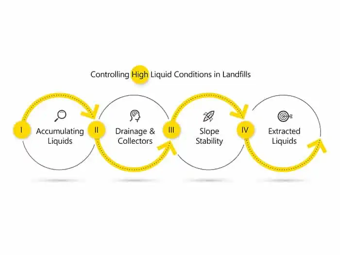
Controlling High Liquid Conditions in Landfills, Part I of IV
There’s a lot of science, engineering, and careful maintenance happening inside and outside of North American landfills. This series of four blogs dive into strategic landfill system integration and the systems balancing act that owners, operators, and their teams manage to control high liquid conditions.
– – – – –
It was once assumed that all (or most) landfill liquids drained to the leachate collection system at the bottom, but increasingly this assumption is not so valid. Rather, liquids accumulate in the waste matrix, posing challenges for landfill owners and operators.
These liquids impair gas extraction as they migrate into gas system extraction features. Wetter conditions in the waste mass reduce slope stability and increase leachate seeps through exposed sideslopes. These factors exacerbate a landfill operators’ ever-present battle with odor control.
High-liquid conditions have escalated at some sites due to recent increasing precipitation trends and the introduction of sludges and other special, wet wastes to offset declining MSW waste streams. Meanwhile, once in contact with waste, liquids become leachate, a costly byproduct to manage (collection, treatment, and disposal). Getting on top of these issues is a top priority for landfill designers, operators, and managers.
Landfill design in theory
Landfills are designed to collect and remove contaminated liquids (leachate) that make their way to the bottom. Designs include a protective liner and a blanket of permeable material such as gravel or sand on top of the liner. Perforated pipes embedded in this permeable blanket drain leachate to low points in each cell for removal, typically through submersible pumps. Or that’s how it works in theory, explains Eric Peterson of SCS Engineers.
“But in reality, the waste near the bottom becomes so dense as it decomposes and compresses naturally that it becomes less and less permeable. The density impedes liquids’ movement through the waste to the leachate collection layer. What liquid doesn’t reach the collection layer sits near the bottom of the landfill or becomes perched between layers of trash, especially ever-increasing quantities of plastic, which create impermeable zones—picture layers of plastic bags and sheeting material interspersed in the waste mass that create multiple zones of perched liquids.
Why else does liquid accumulate in landfills?
In addition to increased liquid levels tied to material density, decomposition, and other waste characteristics, there are contributing factors more related to system design than to the waste itself. One such issue ties to the placement of soil layers on top of the leachate drainage layer.
“Many landfill designers use soil intending to protect the drainage layer and the bottom liner system from damage caused by waste settlement. But that soil becomes compacted and is of low permeability, impeding leachate’s movement out of the waste and into that drainage layer,” explains Bob Dick of SCS Engineers.
He calls out another design-related issue: some operators delay installing the geomembrane final cap and are reluctant to install temporary intermediate exposed caps. These infrastructures are the best defense against infiltration of precipitation, one of the biggest thorns in an operator’s side as they work to stave off excess liquids. Management is becoming harder as precipitation rises, particularly in the Midwest, Northeast, and Mid-Atlantic states experiencing record-breaking rainfalls over the last few years.
The problems posed by liquids naturally occurring in waste and from storms call for robust designs to remove the liquids rather than allowing them to accumulate within the mass.
A few potential solutions
Install a geocomposite drainage net and aggregate of stone or sand and perforated piping at different levels within the waste mass.
This multi-component system collects, and gravity drains leachate to a sump location other than the bottom liner by giving liquids an exit ramp higher up in the landfill. Dick advises placing this system at multiple locations and heights throughout waste lifts, including adding mezzanine collection infrastructure (in the middle of the mass). The idea is for liquids to be captured at different depths, routed to intentional collection points, then removed to short circuit the otherwise tortuous journey for liquids draining through compacted, decomposed waste, daily cover soils, and intermediate covers to reach the bottom.
Aggregate and perforated piping can be of varied configurations; which one you choose depends on multiple factors, such as local availability of stone and aggregate, manpower resources to install and maintain the system, and especially depends on the planned location for the system. Some work well on exterior slopes with lesser volumes of waste and resulting liquids. Others are more suited for interior slopes where waste actively accumulates and generates gas, requiring special features to divert liquids from nearby gas wells. But all have the same overall design concept ─ the idea that liquids will move through the infrastructure on a preferred pathway to the bottom leachate collection layer or mezzanine collection layers.
Install a temporary exposed geomembrane cap and remove it when it’s time to resume waste placement.
Fifteen years ago, installing these temporary caps was uncommon. Operators waited until achieving final grade, then installed a final cap. But Dick says it can take decades to get to final grade. In the meantime, liquid infiltrates the interim soil cover and ultimately saturates waste.
“As we realize the consequences of high-moisture content and excess leachate, more operators are becoming open to investing in these interim caps to reduce the liquid in the waste mass,” he says.
Maintain proper slopes to avoid ponded water.
Rain and melting snow tend to form ponds of water that sit on the landfill’s top deck if it’s flat. With enough accumulation, the liquid drains into the waste. Peterson advises maintaining a deck with at least a 4% slope to facilitate the movement of rainwater and other precipitation off the waste. This is a typical design but is often not implemented. More careful surveying and grading of the waste is needed.
Proactively checking for potential issues
Liquids can accumulate in gas wells, so periodically measuring liquids levels in this infrastructure is a good practice.
“It gives insight into what’s happening with liquid stats and leachate collection system performance that, if impaired from clogging, would block gas collection and impede leachate removal. So, monitoring liquid in vertical wells is a good proactive measure, flagging when you have to work on your leachate system before there is an issue,” Peterson says.
Inspecting leachate drainage pipe cleanouts with cameras should be performed regularly. GIS software can visually display the data and works well to inform operators of their liquids situation.
– – – – –
In Part II of this series, publishing tomorrow, our landfill engineers discuss the impact, mitigating, and controlling liquid-related issues to circumvent three specific problems: gas collection system inefficiencies, slope instability, and leachate seeps.
Corporate Headquarters